Diktator Grinder Installation Guides and FAQ
Find answers to your questions
Diktator MAX 2×72 Tilting Belt Grinder Setup Guide
Table of Contents
- Diktator MAX
- 2x72 Tilting Belt Grinder
-
Section 1:
Tools Required: -
Section 2
Step 1 - Assemble the Uprights and Center Brace - Step 2 - Bolt the Upright Assembly to the Foot Plate
- Step 3 - Assemble the MAX Body Motor Plates
- Step 4 - Assemble the MAX Body Left Body Plate
- Step 5 - Attach the Hinges to the Max Body
- Step 6 - Attach the Base to the Body
- Step 7 - Attach Hinge Handles
- Step 8 - Tracking Arm Hinge
- Step 9 - Gas Strut Side Plates
- Step 10 - Gas Strut Installation Top
- Step 10b - Gas Strut Installation Bottom
- Step 11 - Install the Control Arm Handle
- Step 12 - Install Tracking Wheel Adjusting Knob
- Step 13 - Install Tracking Wheel Adjusting Knob
- Step 14 - Assemble and Attach the Tracking Wheel
- Step 15 - Install the Tooling Arm and Handles
- Step 16 - Install the D-Plate
- Step 17 - Install the Platen Bracket
- Step 18 - Install the Platen
- Step 19 - Assemble and Install the Idler Wheels
-
Section 3:
Diktator MAX - Parts Packing List (Box 1) - Diktator MAX - Parts Packing List (Box 2)
-
Section 4
Basic Installation & Use Instructions -
Section 6:
Troubleshooting and Maintenance Guide
Diktator MAX
2x72 Tilting Belt Grinder
Assembly Instructions
Version 2.07
|
|
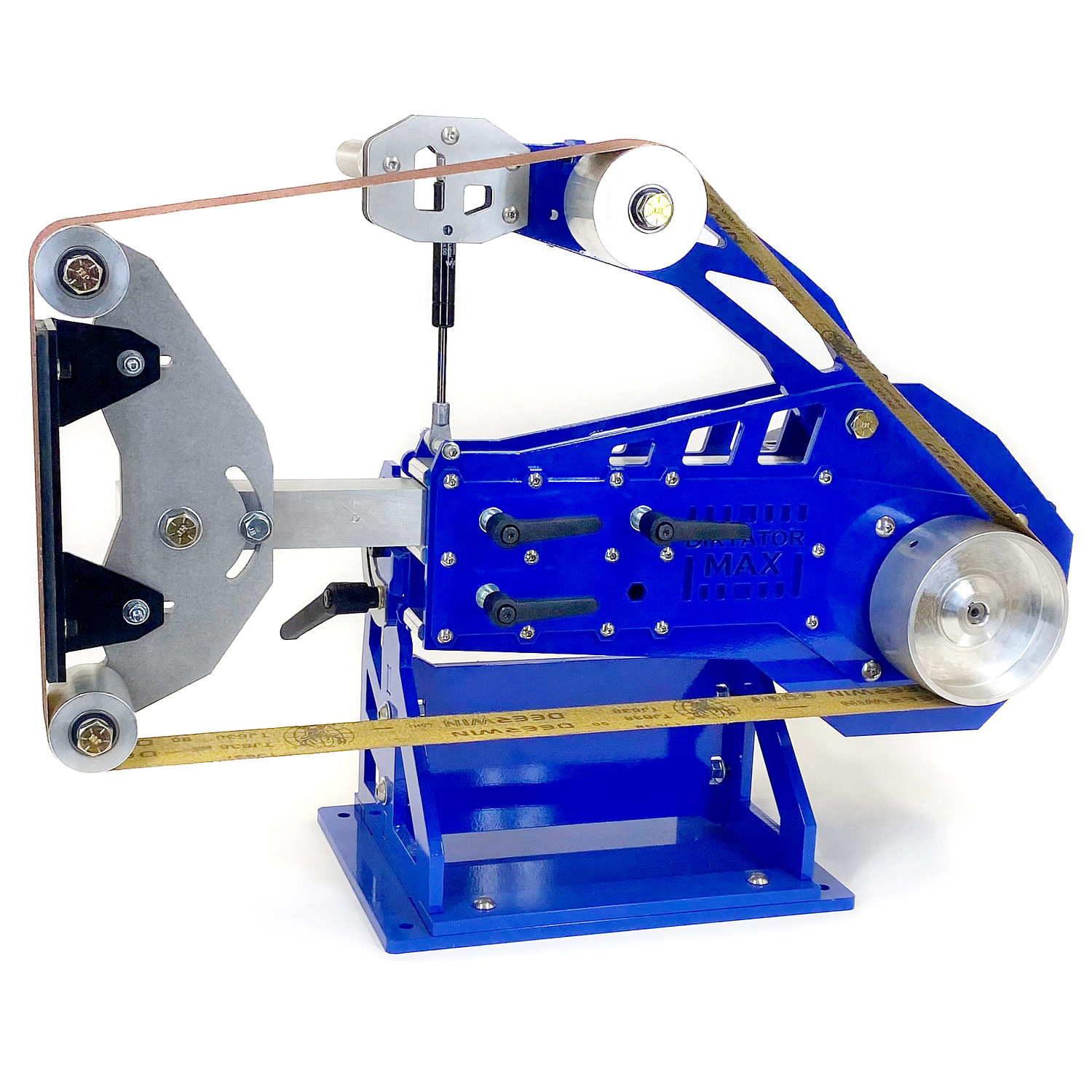
Table Of Contents:
Section 2
Step 1 - Assemble the Uprights and Center Brace 5
Step 2 - Bolt the Upright Assembly to the Foot Plate 6
Step 3 - Assemble the MAX Body Motor Plates 7
Step 4 - Assemble the MAX Body Left Body Plate 9
Step 5 - Attach the Hinges to the Max Body 10
Step 6 - Attach the Base to the Body 12
Step 7 - Attach Hinge Handles 15
Step 8 - Tracking Arm Hinge 16
Step 9 - Gas Strut Side Plates 17
Step 10 - Gas Strut Installation Top 18
Step 10b - Gas Strut Installation Bottom 20
Step 11 - Install the Control Arm Handle 22
Step 12 - Install Tracking Wheel Adjusting Knob 23
Step 13 - Install Tracking Wheel Adjusting Knob 25
Step 14 - Assemble and Attach the Tracking Wheel 26
Step 15 - Install the Tooling Arm and Handles 28
Step 16 - Install the D-Plate 31
Step 17 - Install the Platen Bracket 32
Step 18 - Install the Platen 33
Step 19 - Assemble and Install the Idler Wheels 34
Section 3:
Diktator MAX - Parts Packing List (Box 1) 36
Diktator MAX - Parts Packing List (Box 2) 38
Section 4
Basic Installation & Use Instructions 40
Section 6:
Troubleshooting and Maintenance Guide 43
Section 1:
Tools Required:
|
|
|
IMPORTANT! |
Never use any power tools during kit assembly! Always wear safety glasses |
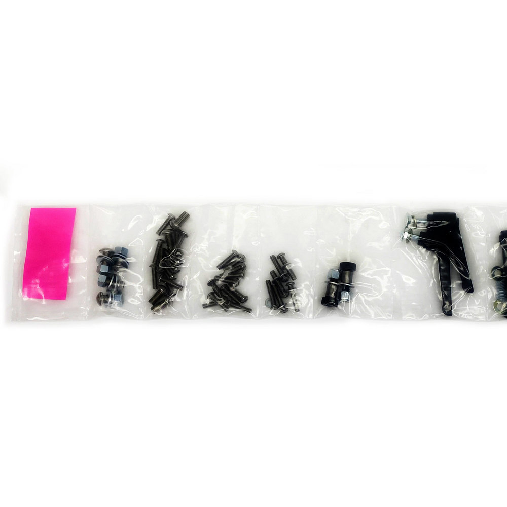
Start With The Fastener Pack
|
|
|
Layout the fastener kit on a bench as shown with the PINK slip on the LEFT. Open the bolt compartments one at a time from LEFT to RIGHT. First, ensure that you identify the bolts for each step before taking them out of the pack |

|
PRO-TIP |
Each set of steps requires one compartment from the Fastener kit. Only open one compartment at a time. |
|
|
|
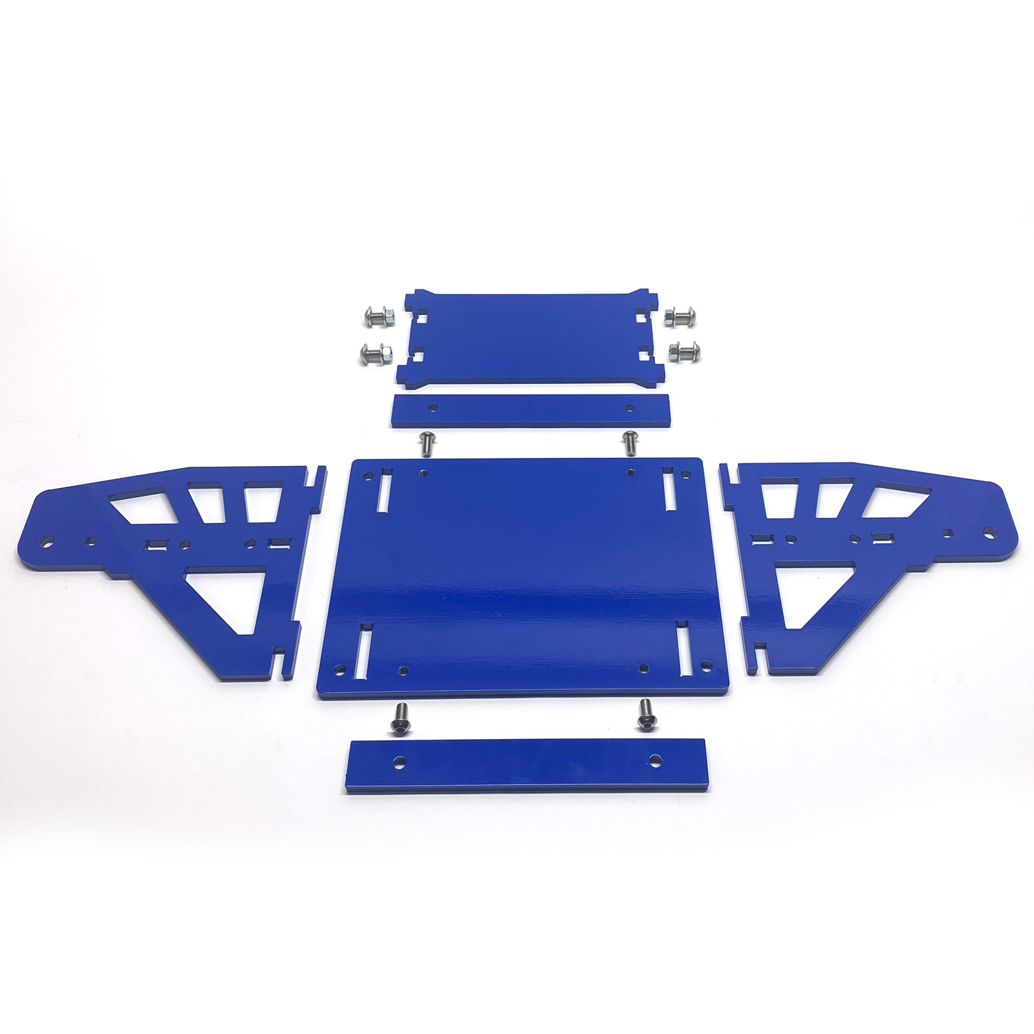
Base Parts:
|
Section 2
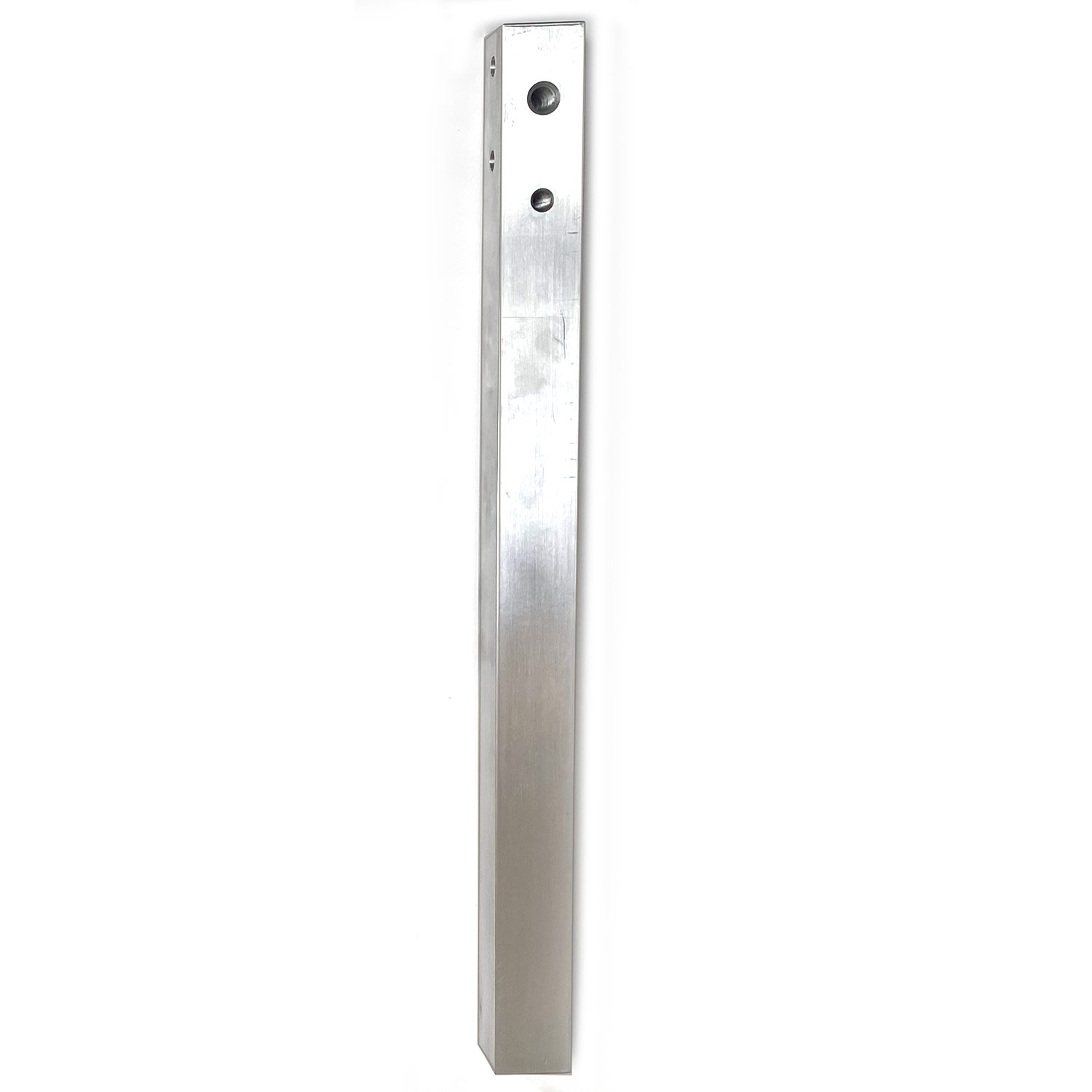
Step 1 - Assemble the Uprights and Center Brace
Use Bolt Pack 1
|
|
|
|
01.1 - Begin assembling by connecting (insert) the Center Brace into one Upright as pictured. The Center Brace and Uprights are Universal, meaning they can connect anyway, (there is no left or right) |
01.2 - Insert the bolt with the washer from the outside, use one washer, and bolt on the cutout. Just hand tight at the point. Repeat the step for the other 3 bolts and nuts. Make sure the uprights can 'wiggle' a bit for now. |
|
|
|
|
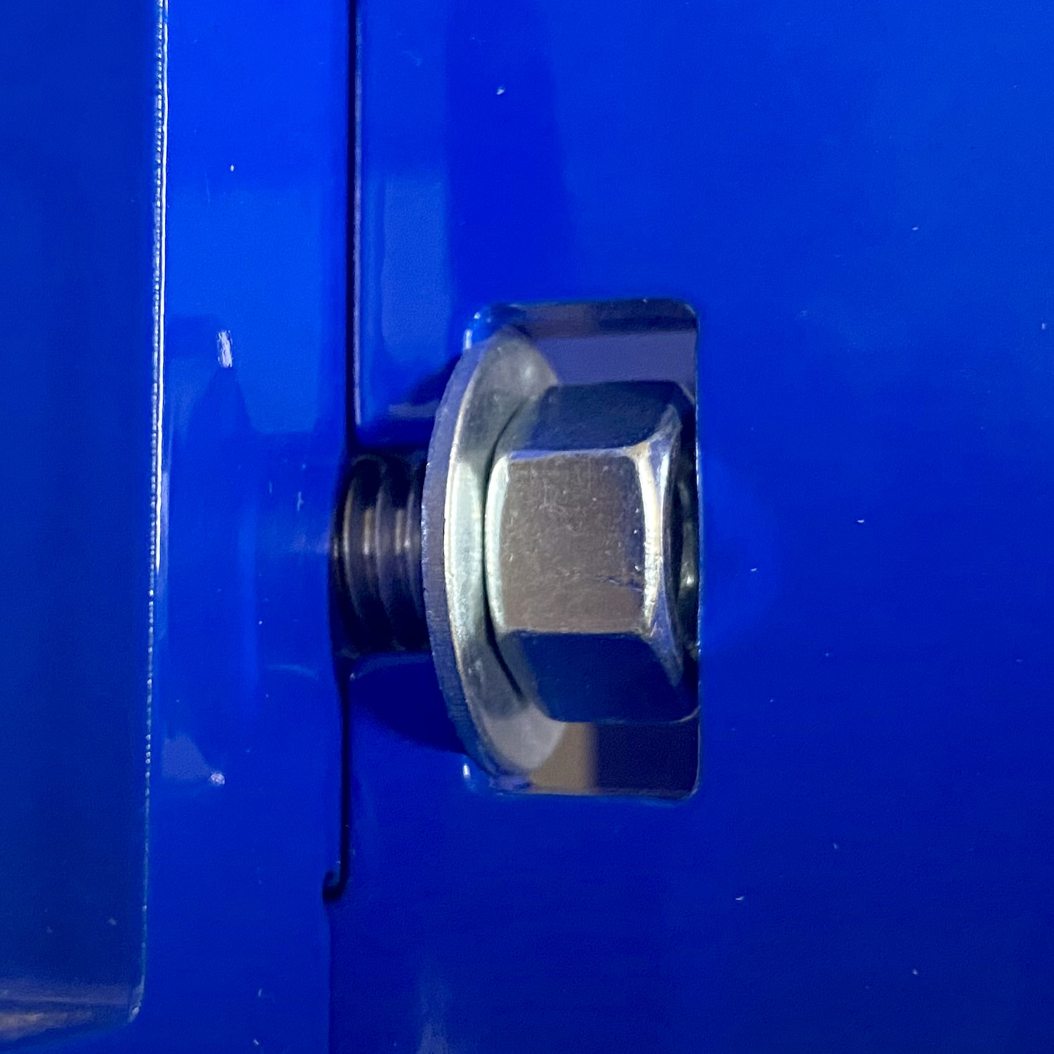
01.3 - Close up of the Nut with Washer. Insert the remaining Upright. |
01.4 - Make sure it mirrors the first UPRIGHT. Install the two remaining bolts and nuts. Once complete it should look like the picture above (bolts slightly loose still) |
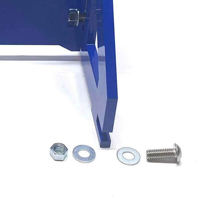
Step 2 - Bolt the Upright Assembly to the Foot Plate
Use Bolt 2
|
|
|
|
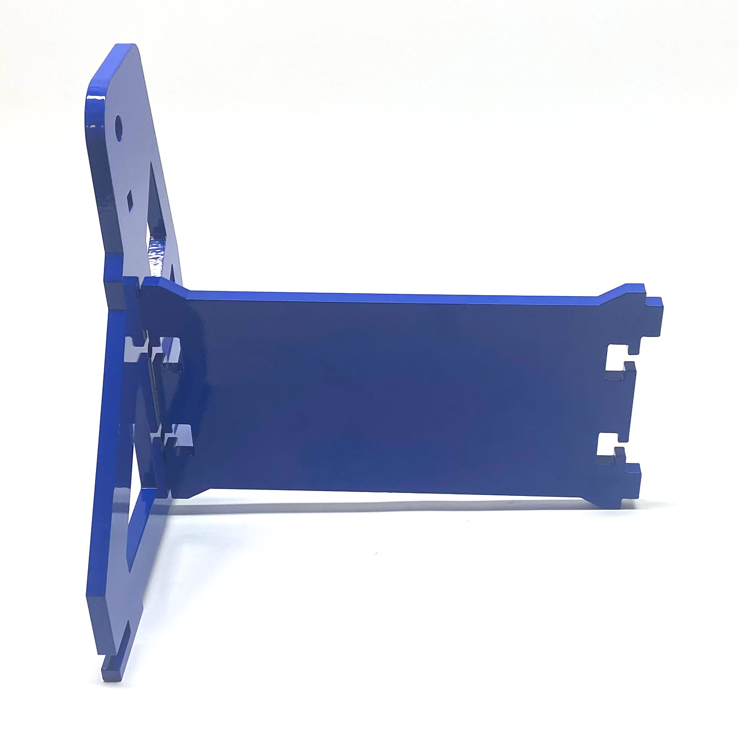
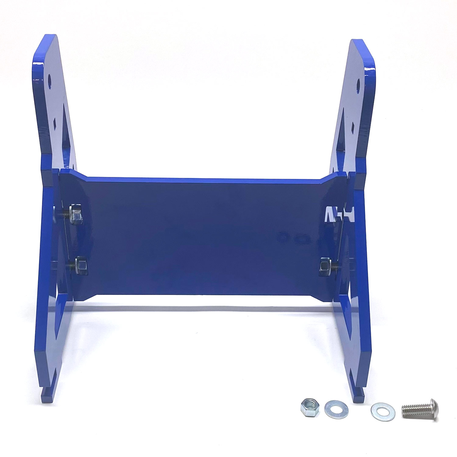
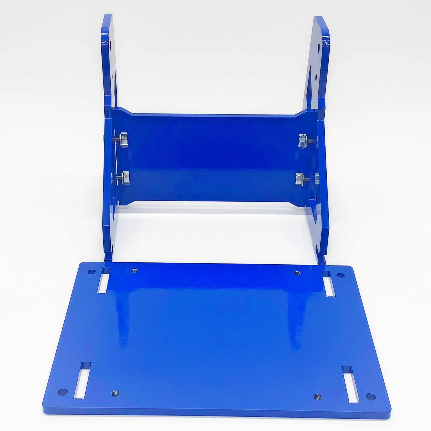
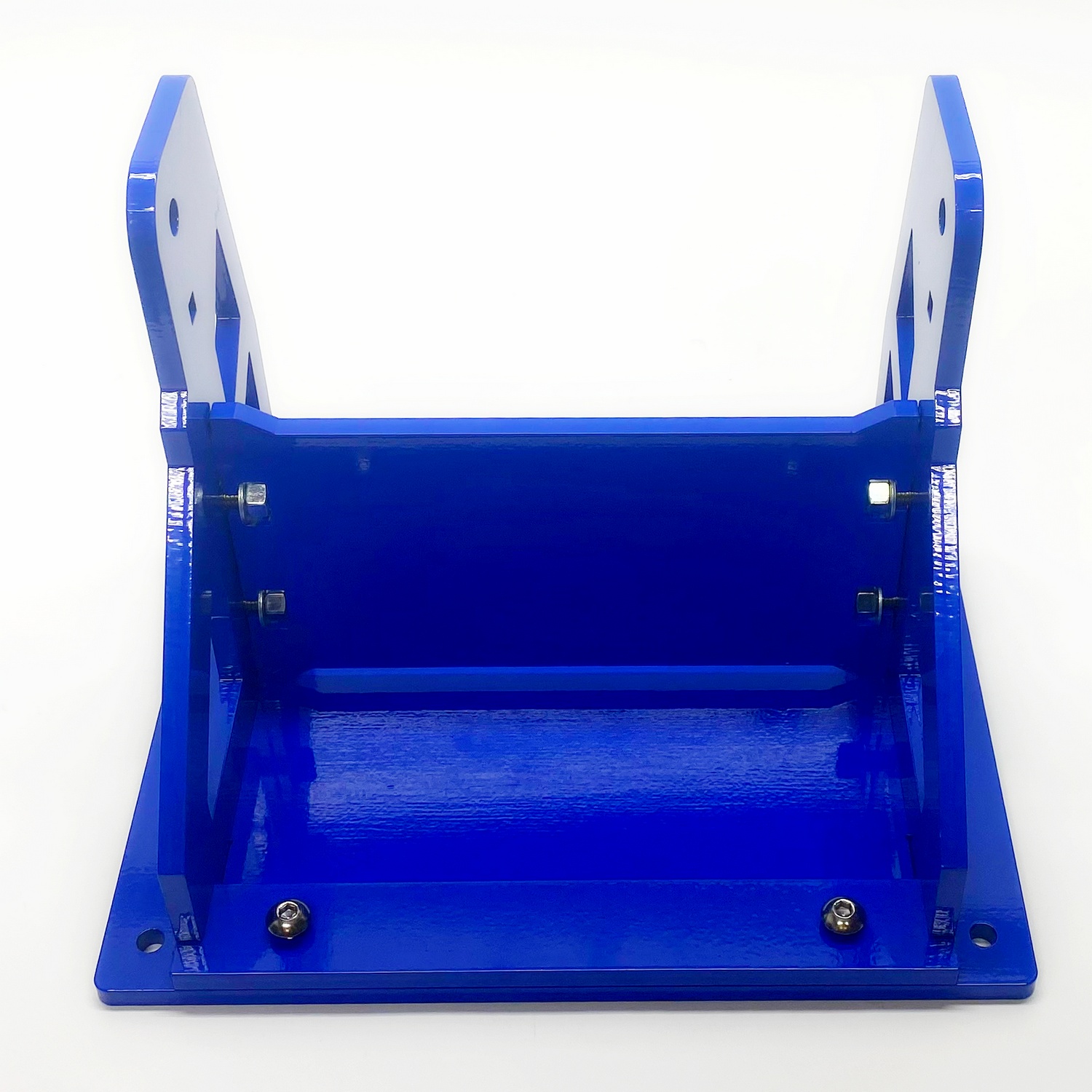
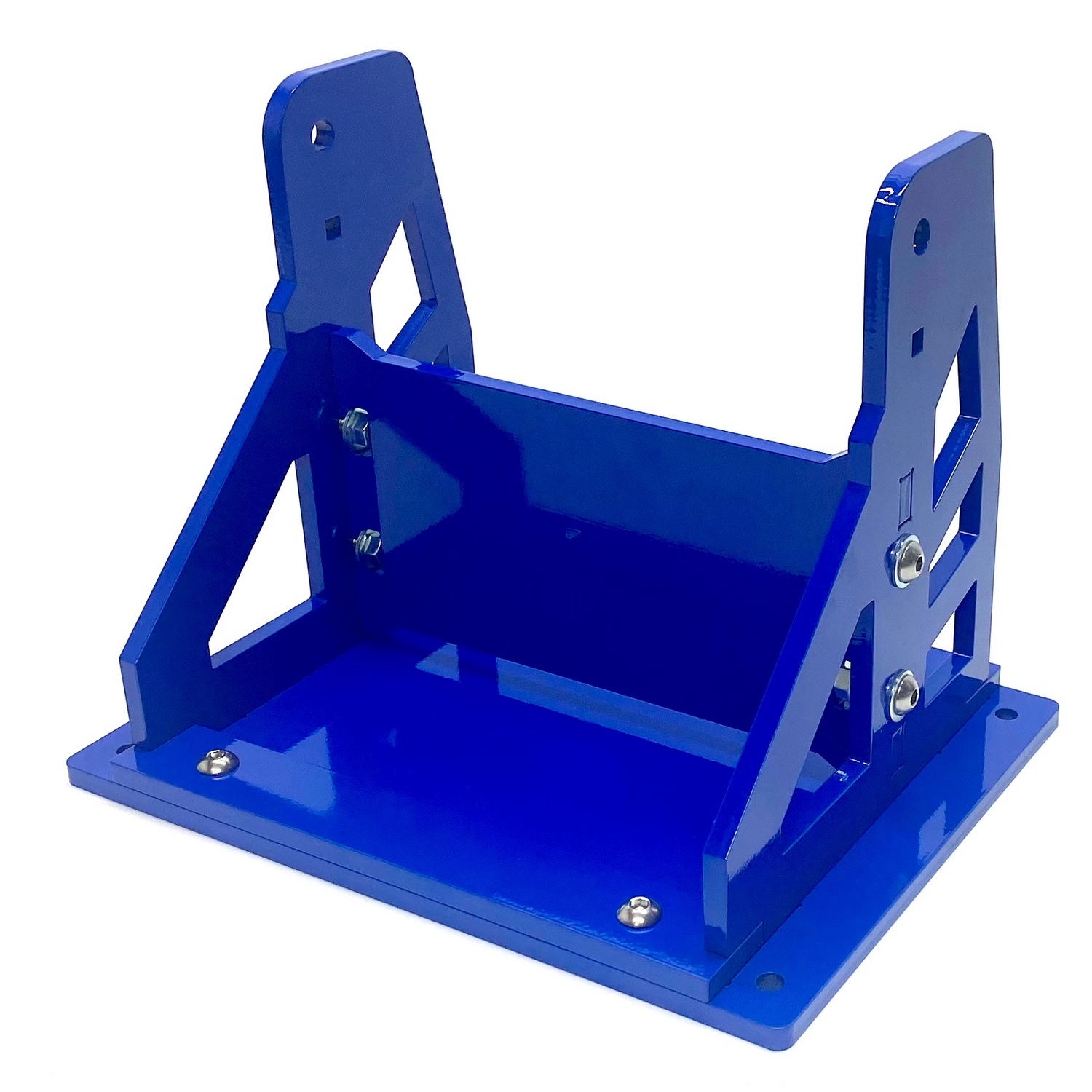
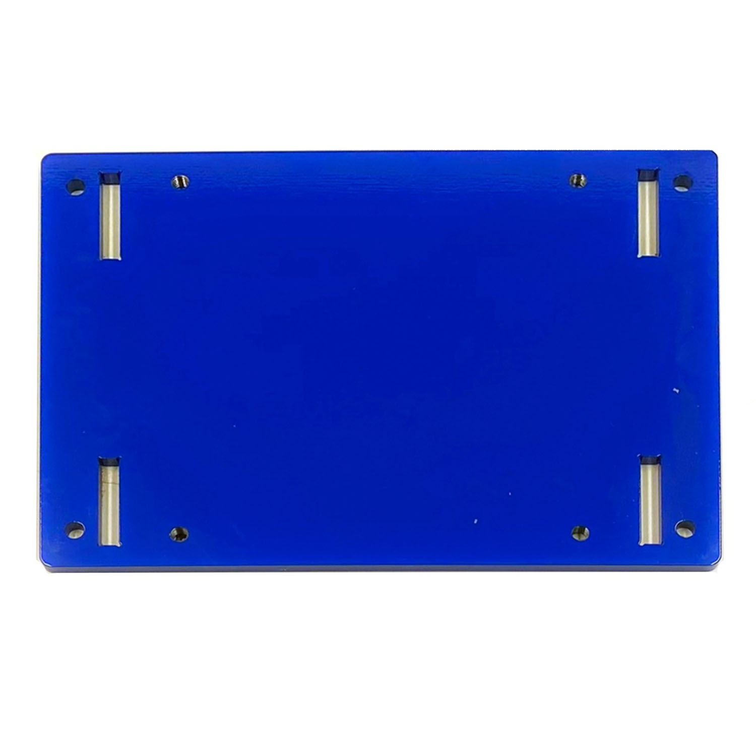
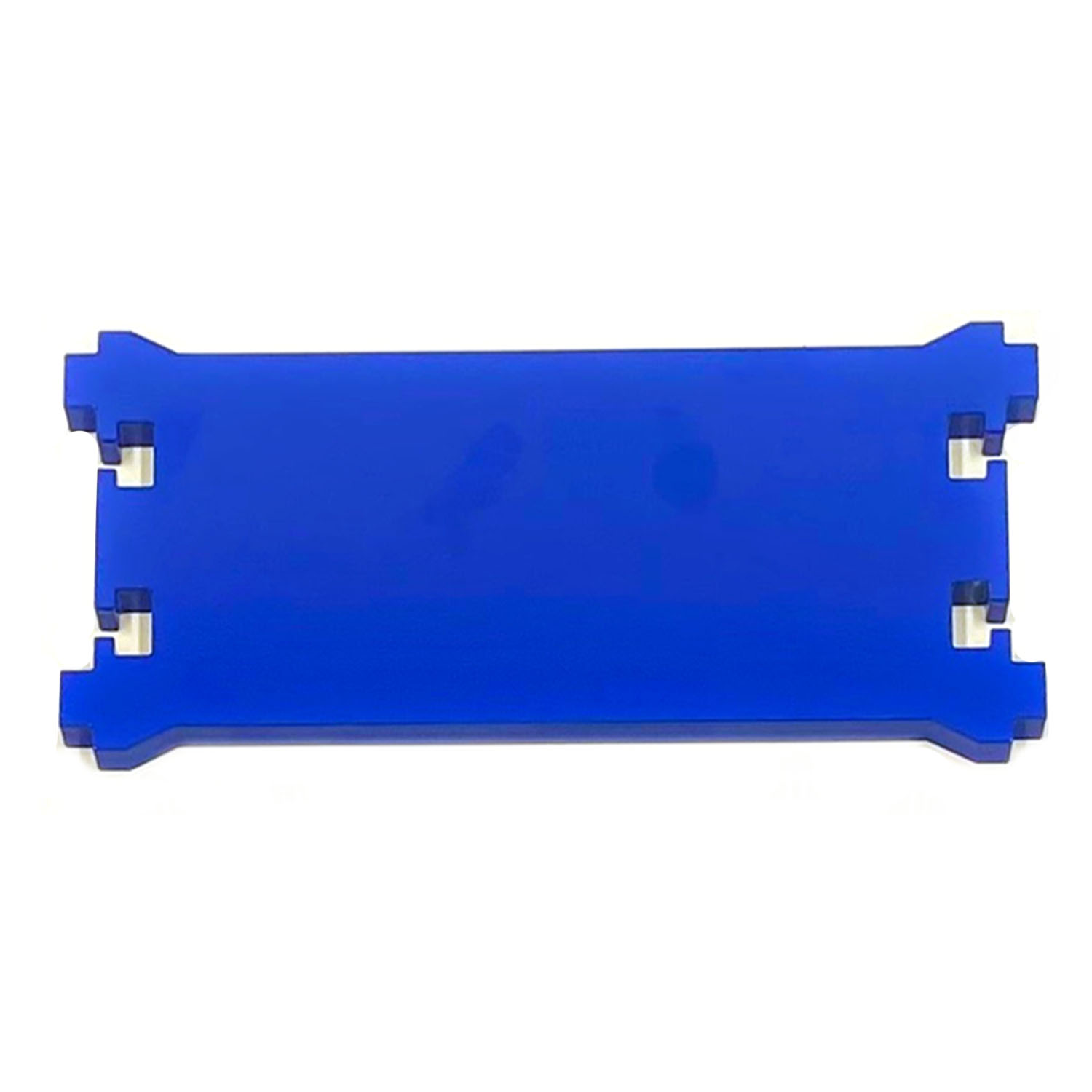
02.1 - Insert the assembled Upright into the Footplate slots. The Footplate is Universal, meaning there is no Front, Right, Top or Bottom. |
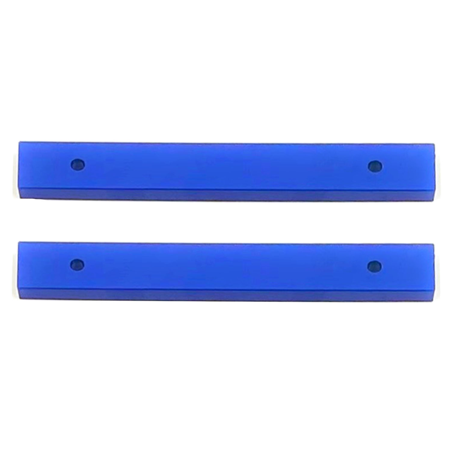
02.2 - Install the Pull Down Bar between the Footplate and the Uprights. |
|
|
|
|
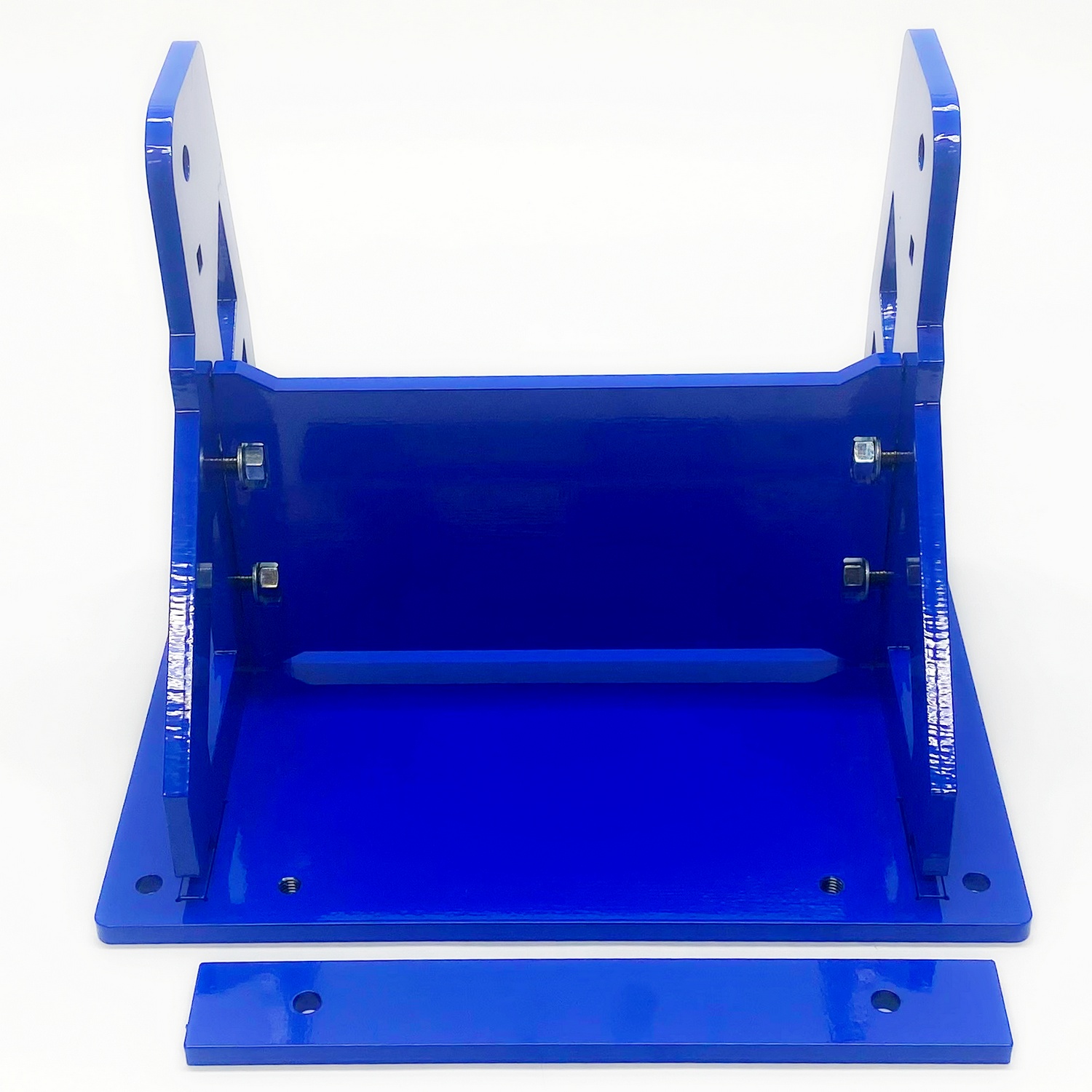
02.3 - Install the bolts into the Footplate. Hand-tight and repeat the steps for the remaining Pull-Down Bar (bolts still slightly loose) |
02.4 - Your Base should resemble the last picture above. Now you can fully tighten the bolts that connect the Uprights to the Center Brace. Next, tighten the bolts on the Pull-Down Bars. Set the base assembly aside |
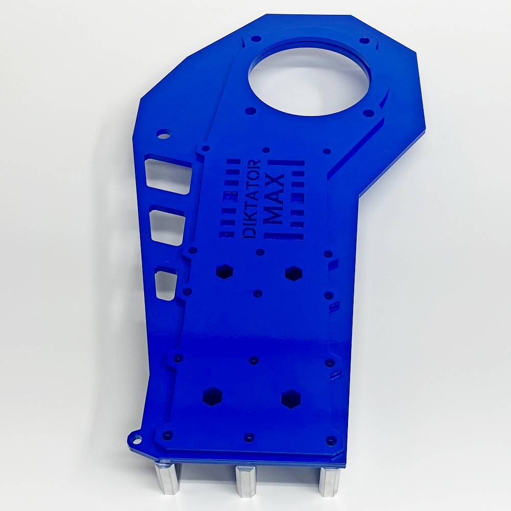
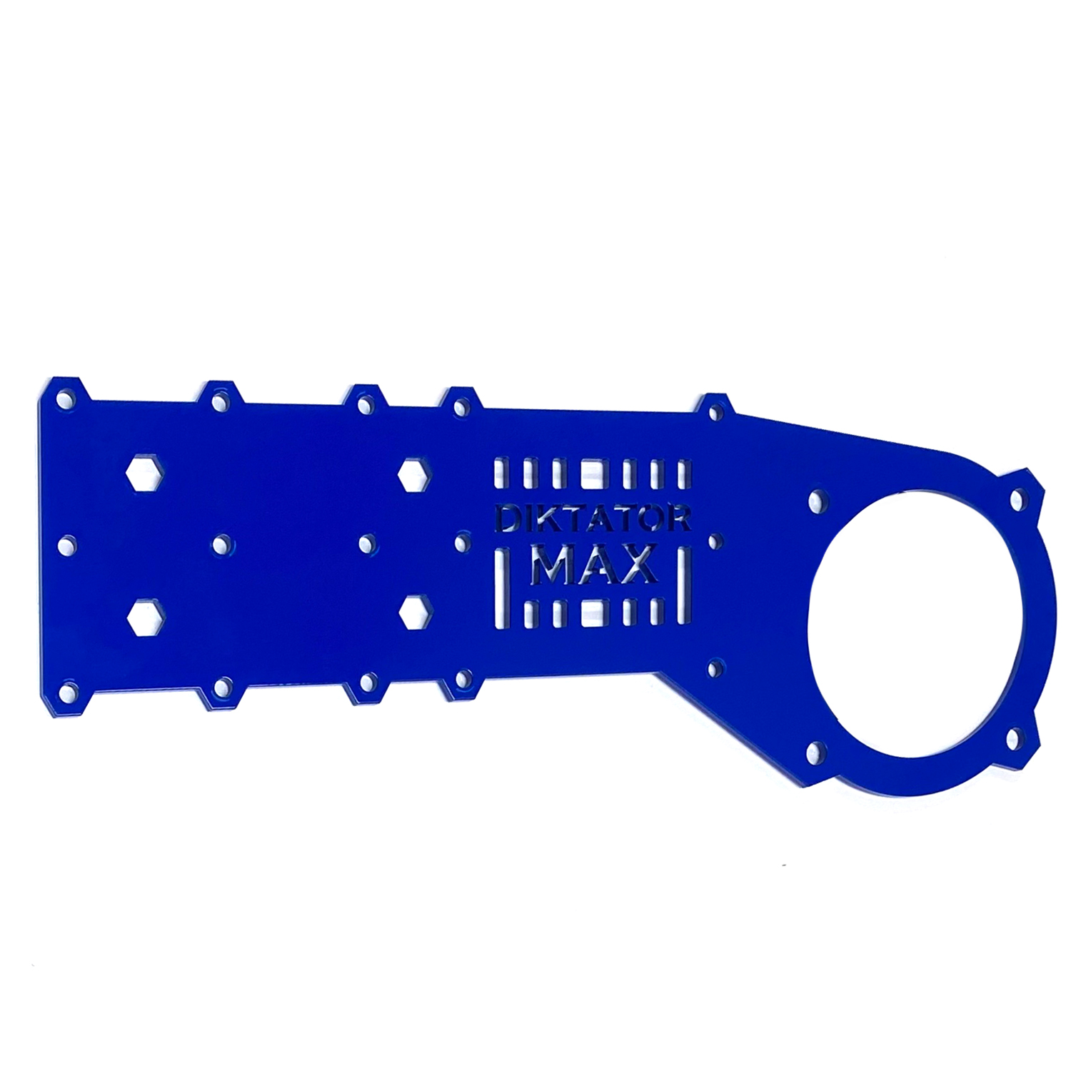
Step 3 - Assemble the MAX Body Motor Plates
Use Bolt Pack 3
|
|
|
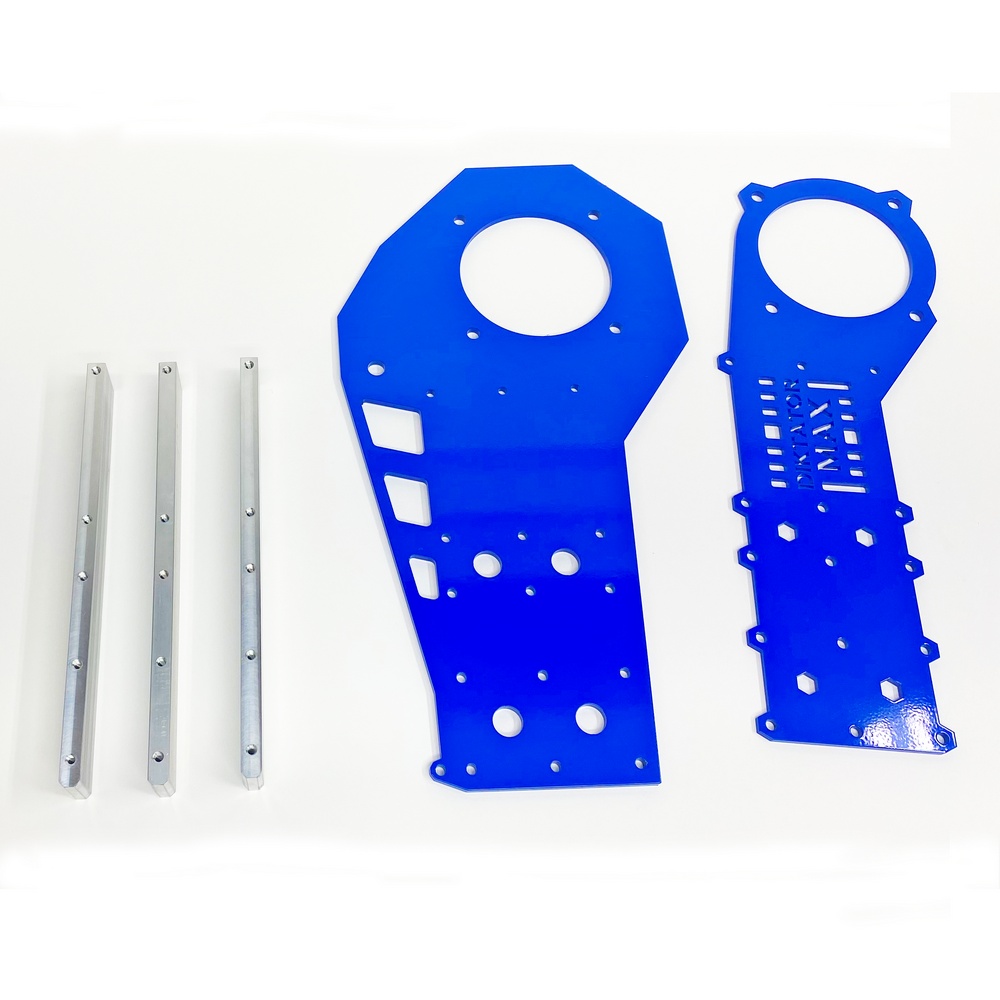
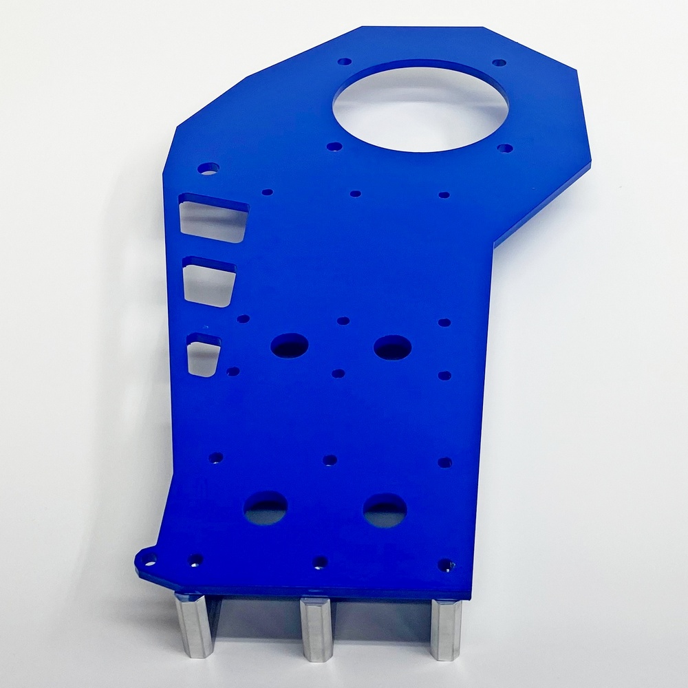
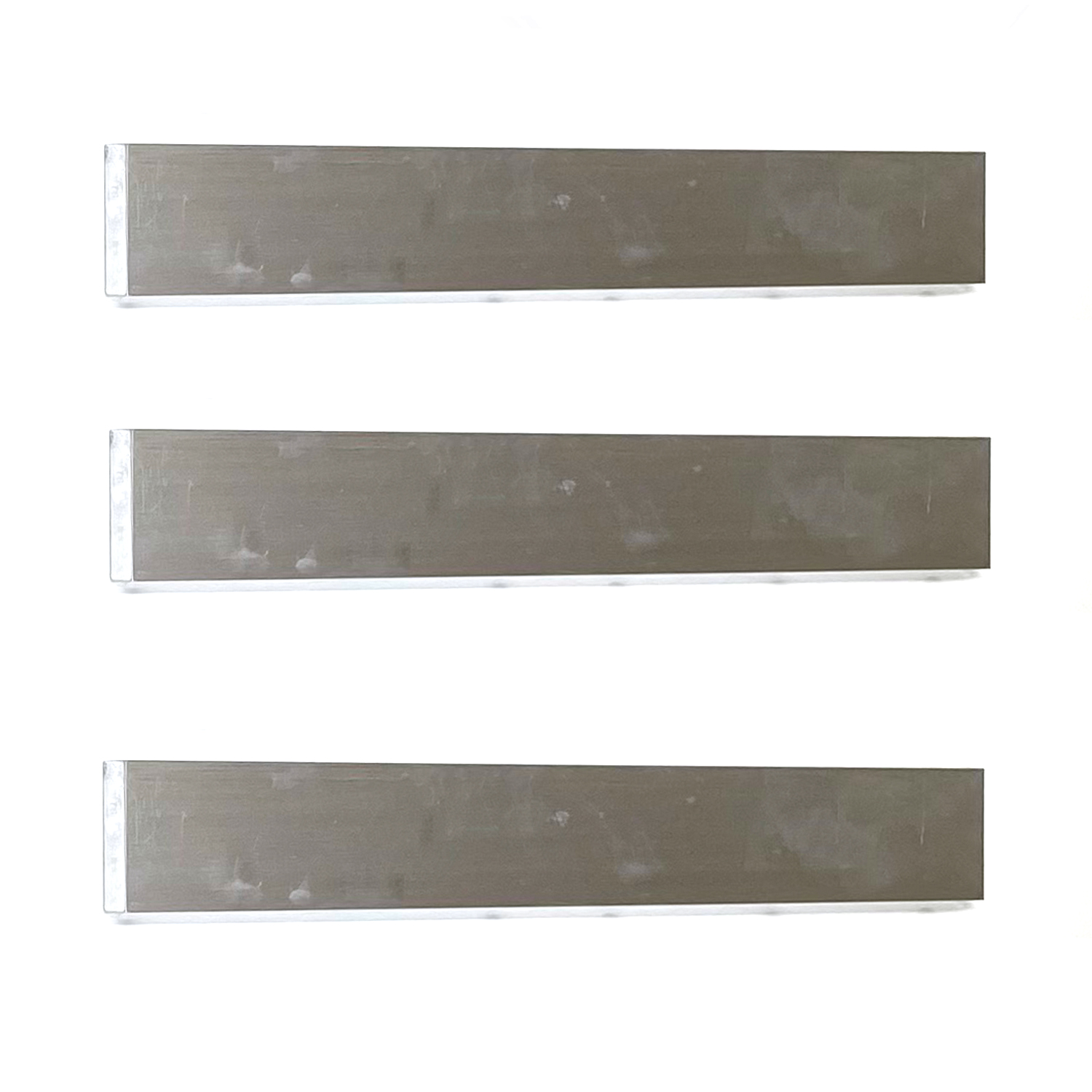
03.1 - Start assembling the Motor Plate to the Aluminum Spacers
|
|
|
|
|
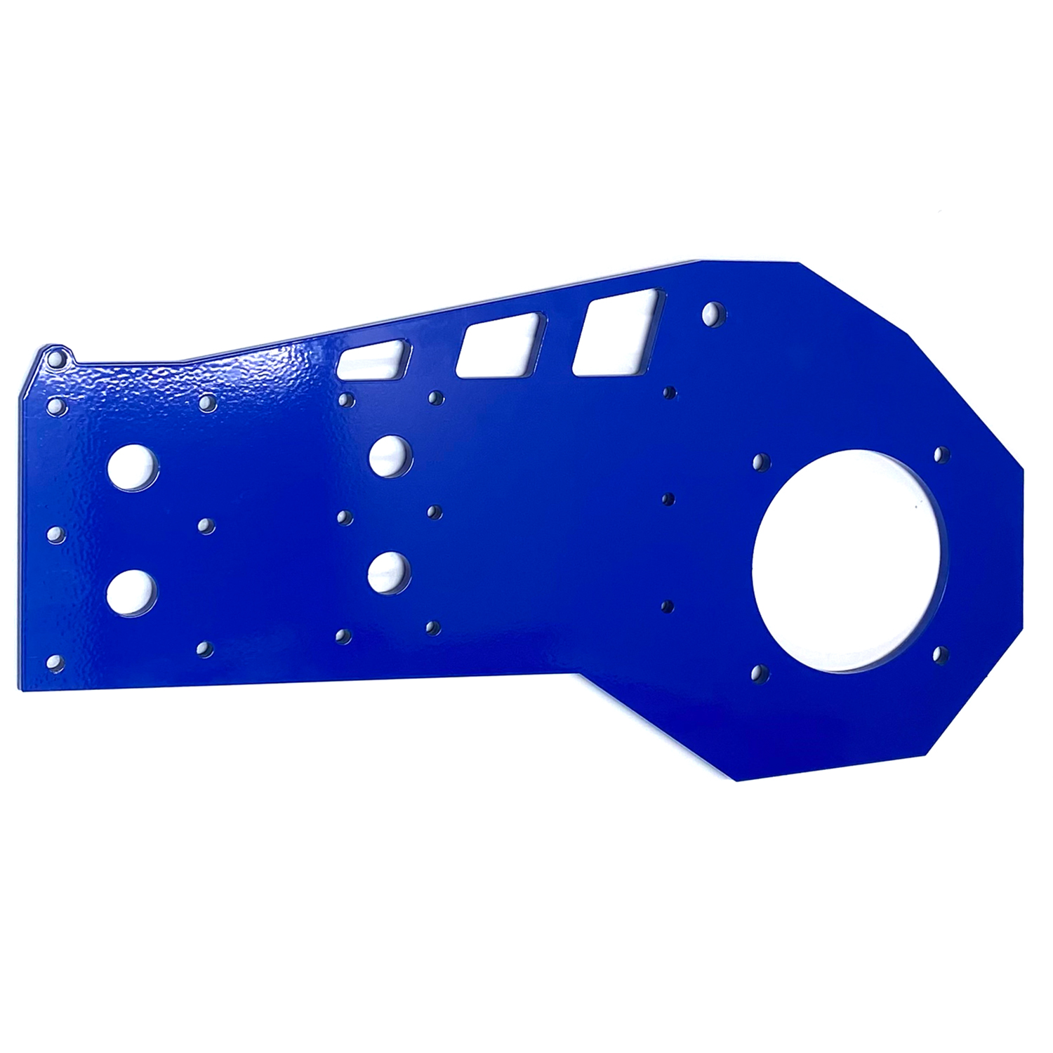
03.2 - Place the Large Motor Plate on top of the Aluminium guides |
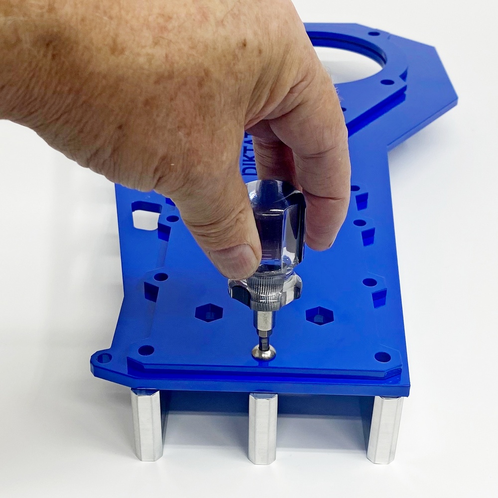
03.3 - Place the Small Motor Plate on top of the large motor plate and insert the center screw (Don’t use power tools) |
|
|
|
|
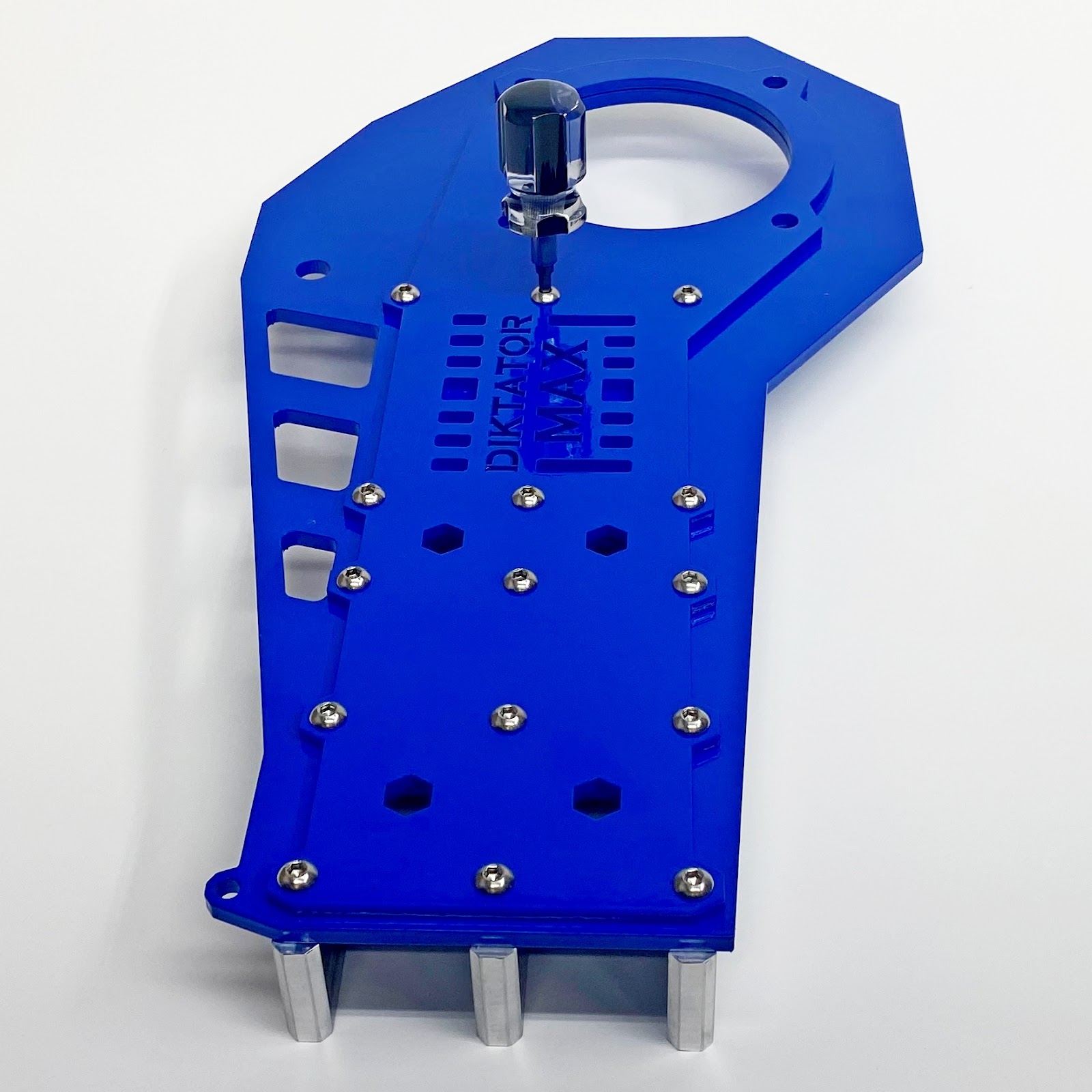
03.4 - Align the holes and insert the first bolt, only screw it in halfway. Now screw in the rest of the bolts (only halfway) |
03.5 - Once all the bolts are screwed in, you can fully tighten them (don't use power tools). |
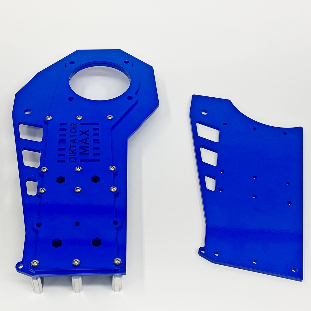
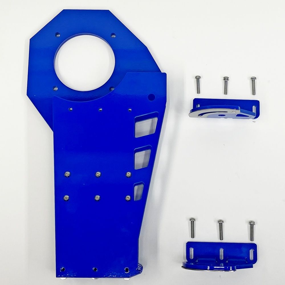
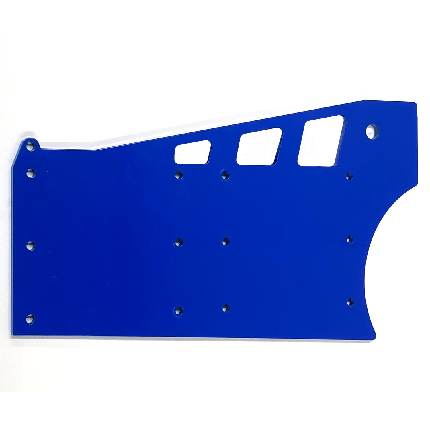
Step 4 - Assemble the MAX Body Left Body Plate
Use Bolt Kit 4
|
|
|
|
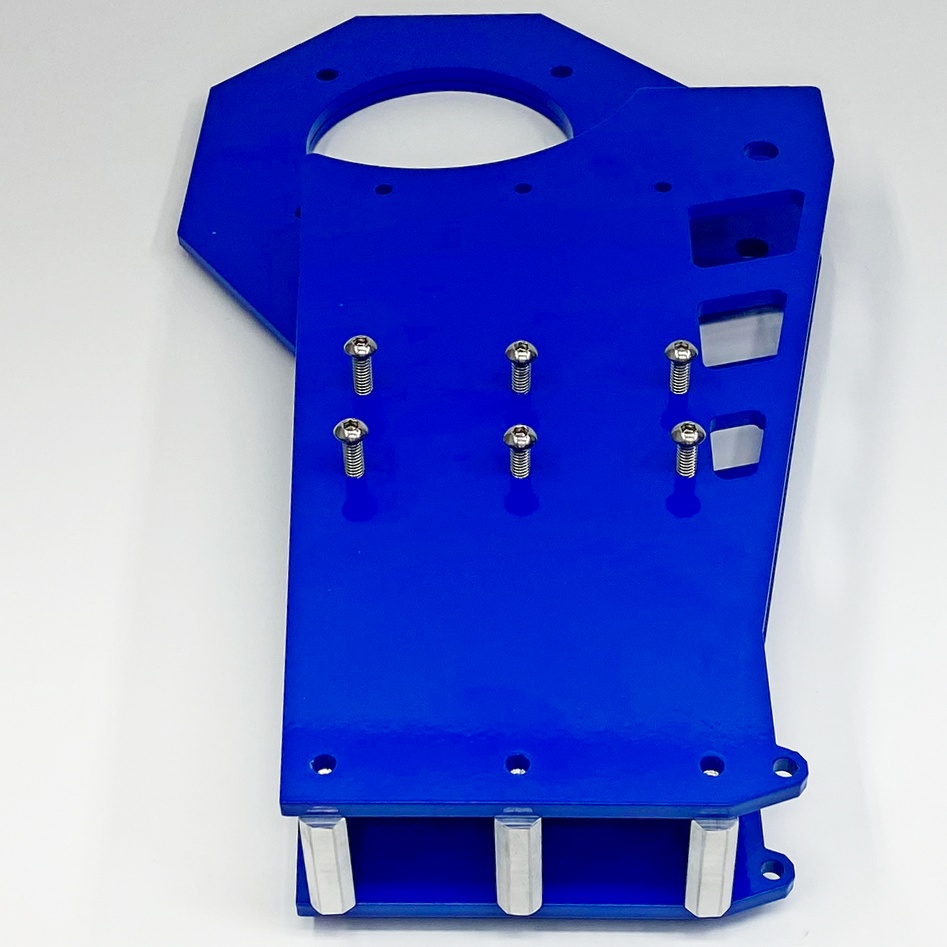
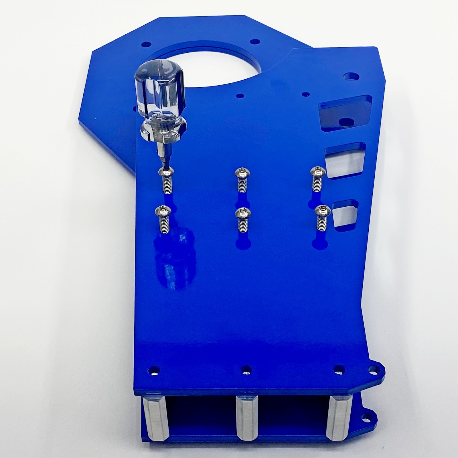
04.1 - Turn the assembled motor plate over and put the remaining body plate on top, see next picture |
04.2 - Now install the six center bolts as pictures. |
|
|
|
|
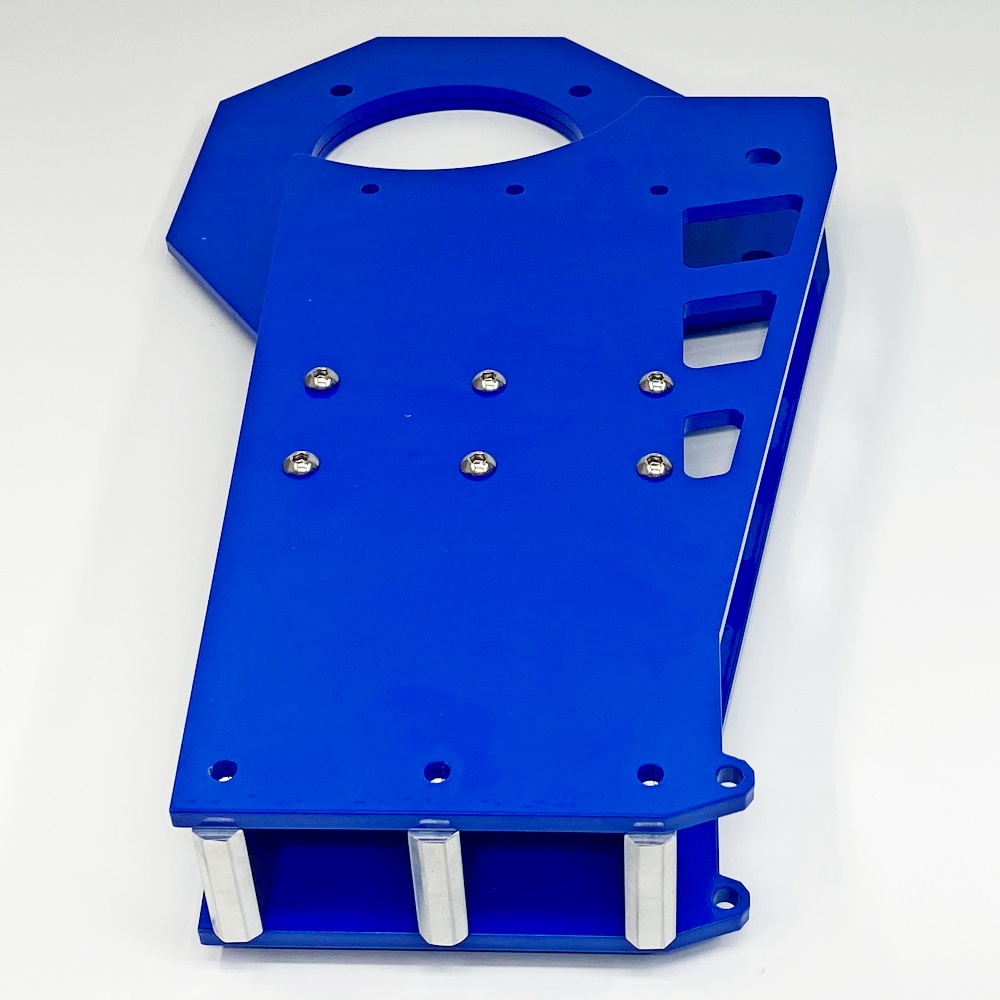
04.3 - IMPORTANT! don’t use power tools. |
04.4 - Tighten all the bolts down |
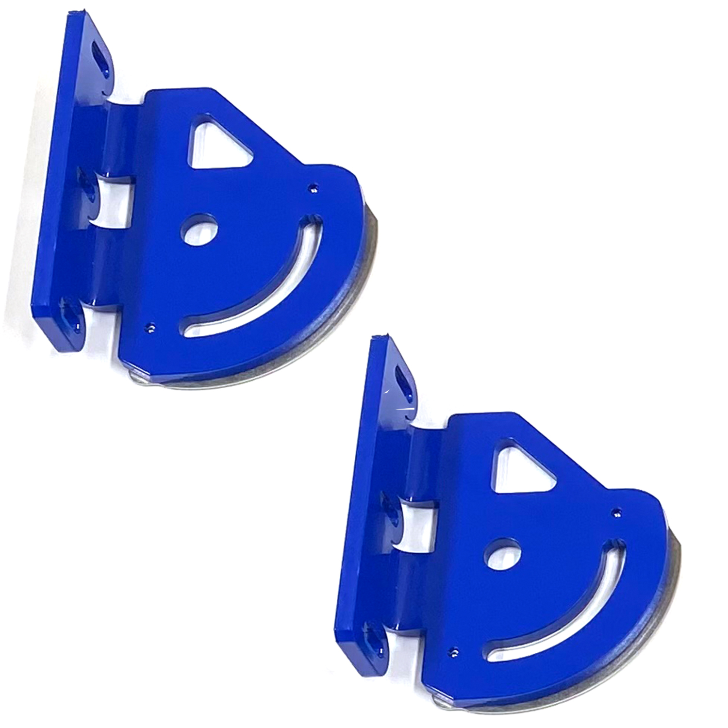
Step 5 - Attach the Hinges to the Max Body
Use Bolt Kit 5
|
|
|
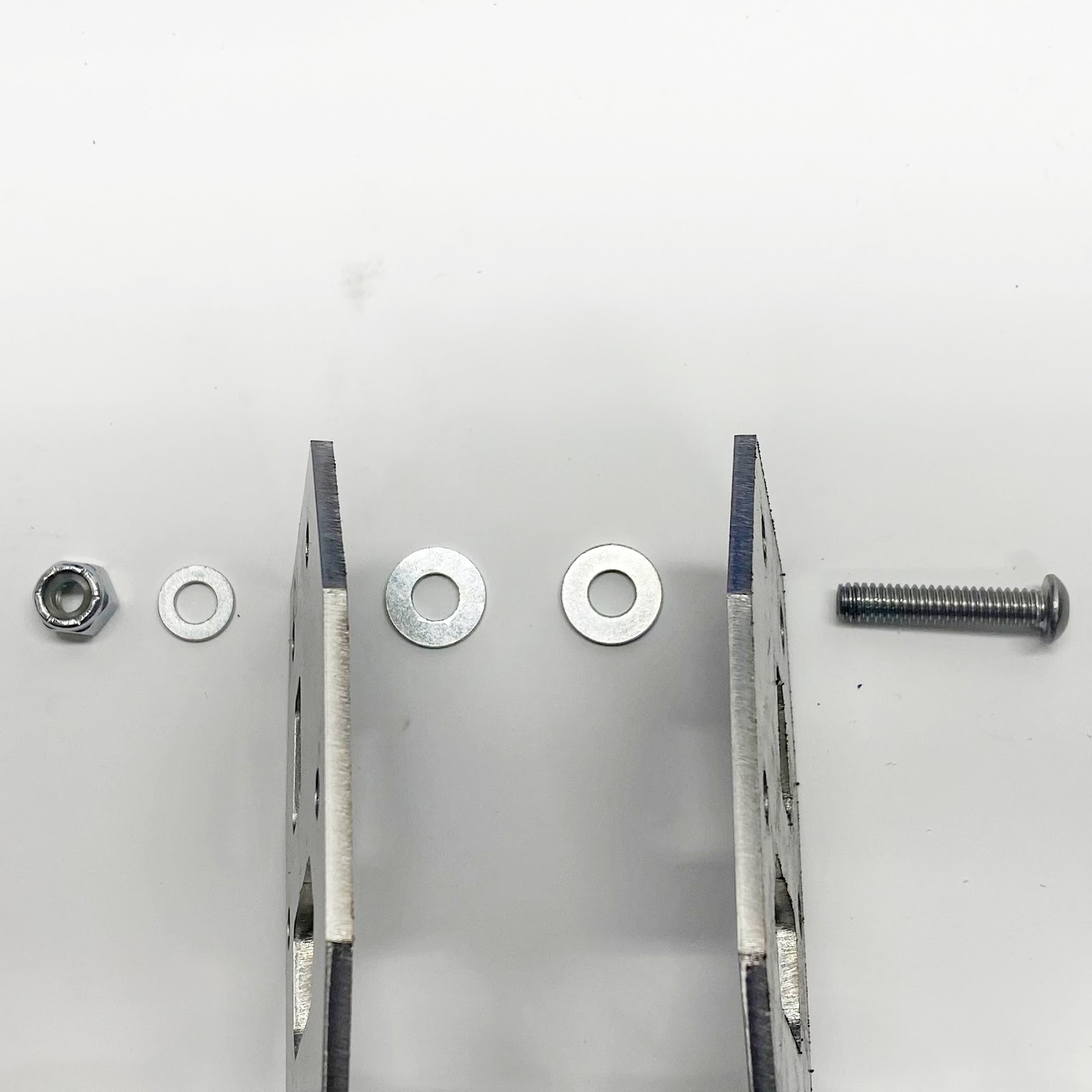
5.1 - Layout the parts as pictured. Note: the washers are on the bolts |
|
|
|
5.2 - Only tighten the bolts down about 3/4 of the way, make sure hinges can slide back and forth to adjust for the width of the base. Use a square to see if the hinges are at a 90* angle to the body. If the hinges aren’t 90* you can give it one or two strikes with a rubber mallet until it is at 90* |
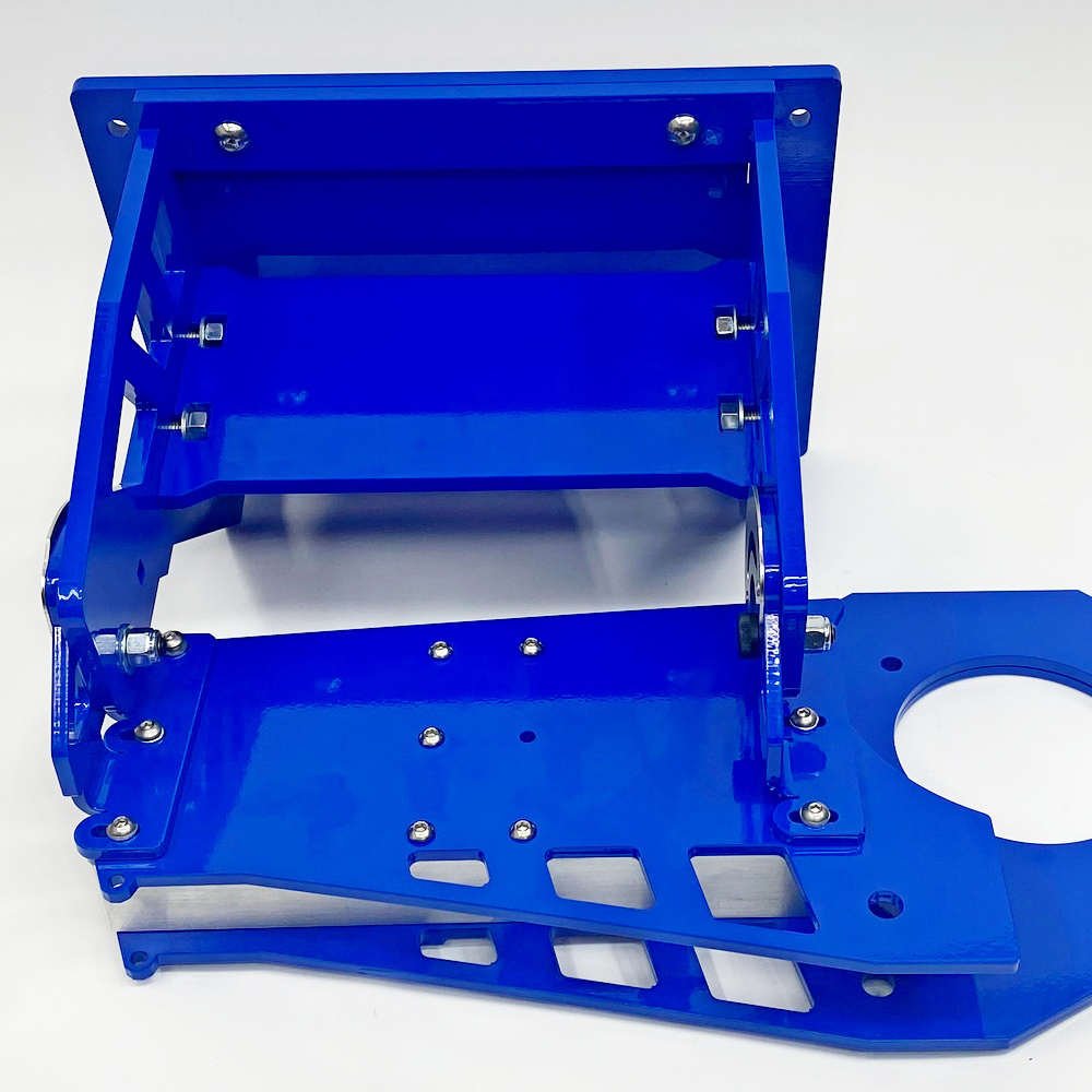
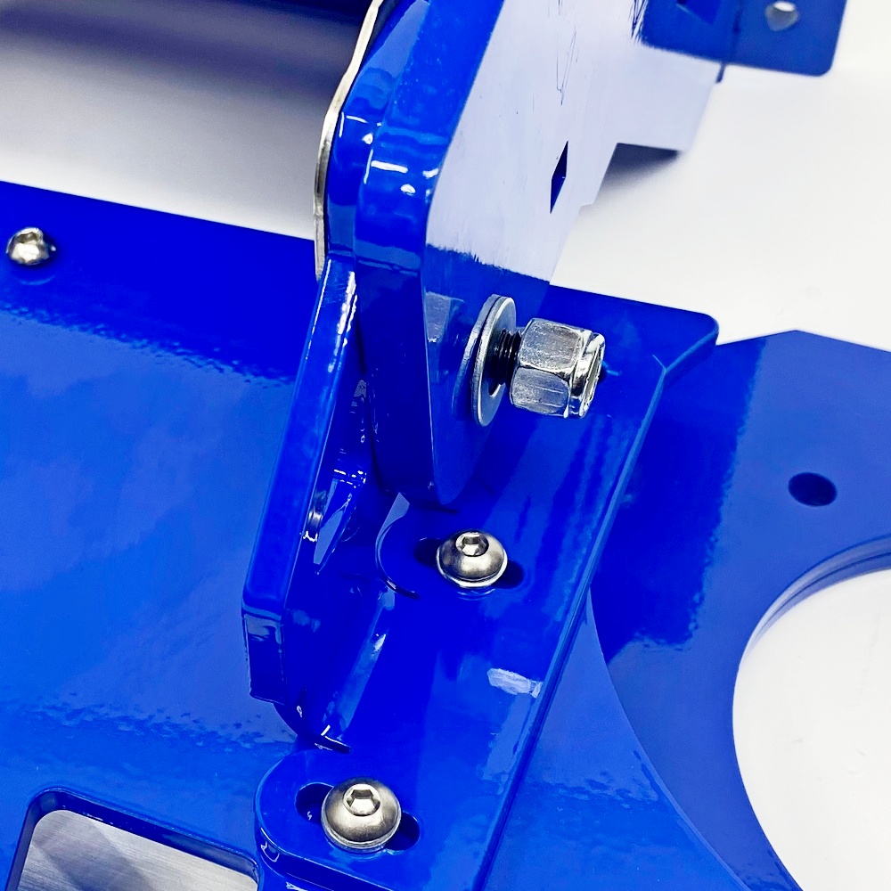
Step 6 - Attach the Base to the Body
Use Bolt kit 6
|
|
|
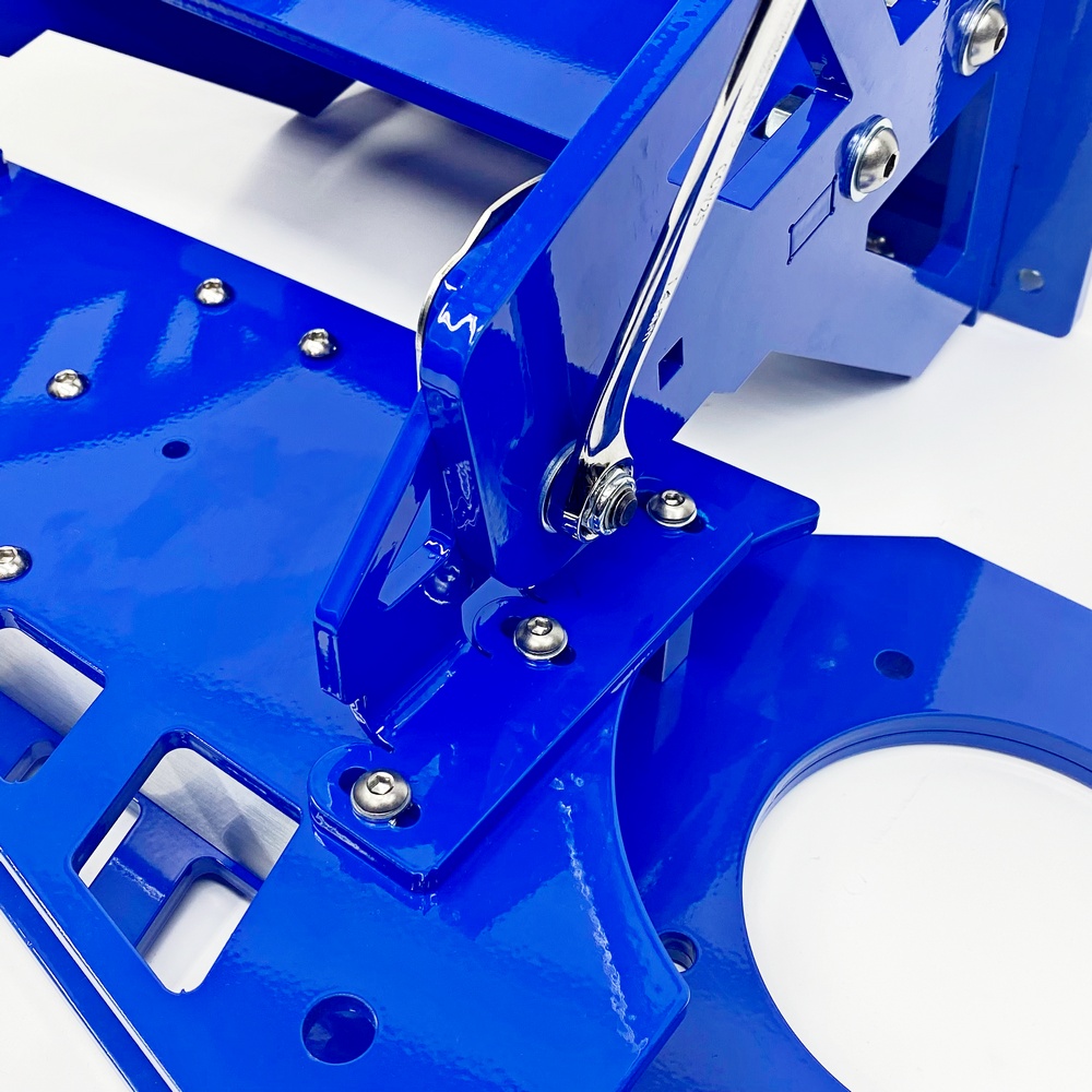
06.1 - Place the base next to the body so that when you tilt the base towards the body the holes for the hinges would line up, insert the shoulder bolts (see next step). |
|
|
|
06-2 - Insert the shoulder bolt into the hinge to connect the body to the base, repeat this for both hinges. In some cases, you might have to use a mallet to get the bolts in if the paint is a little thick. |
|
|
|
|
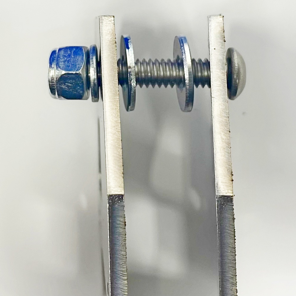
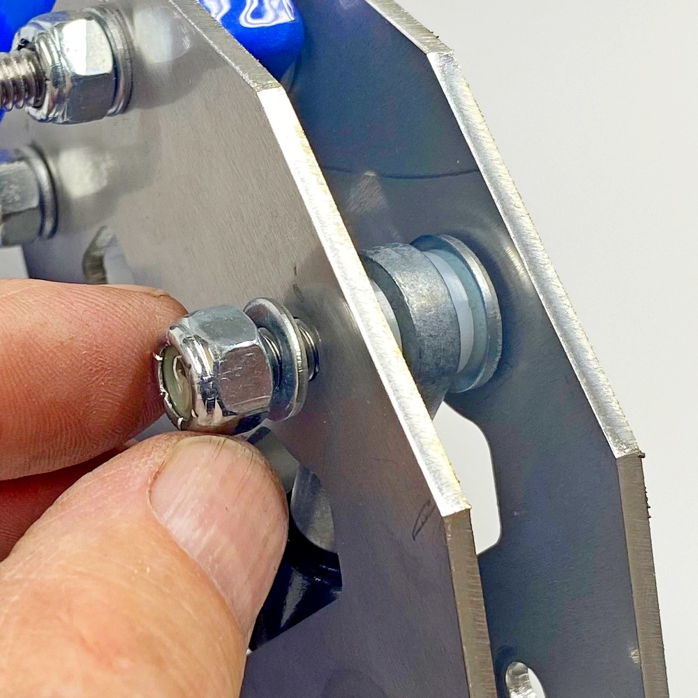
06.2 - Insert the washer and lock nut |
06.3 - Tighten the nut to align the hinges to the upright |
|
|
|
|
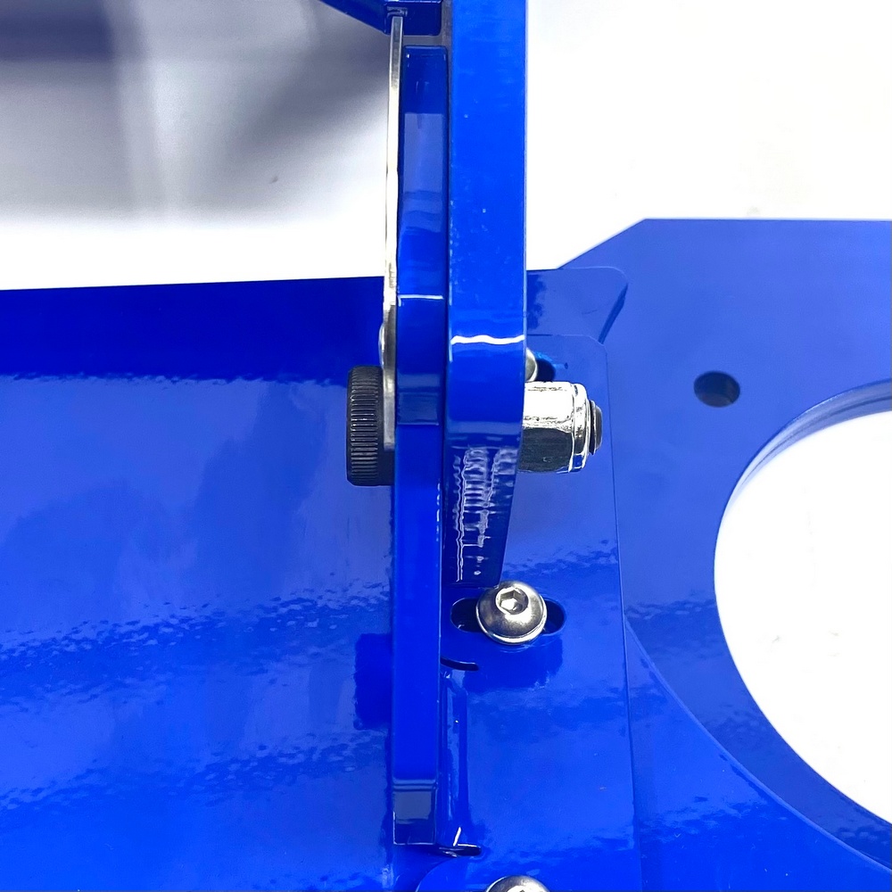
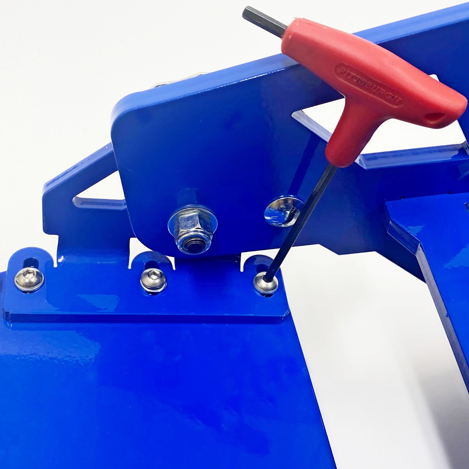
06.4 - Tighten the nut so there is no clearance, this is to align the hinge to the base. |
06.5 - Next fully tighten the bolts that connect the hinges to the body |
Step 7 - Attach Hinge Handles
Bolt Kit 7
|
|
|
|
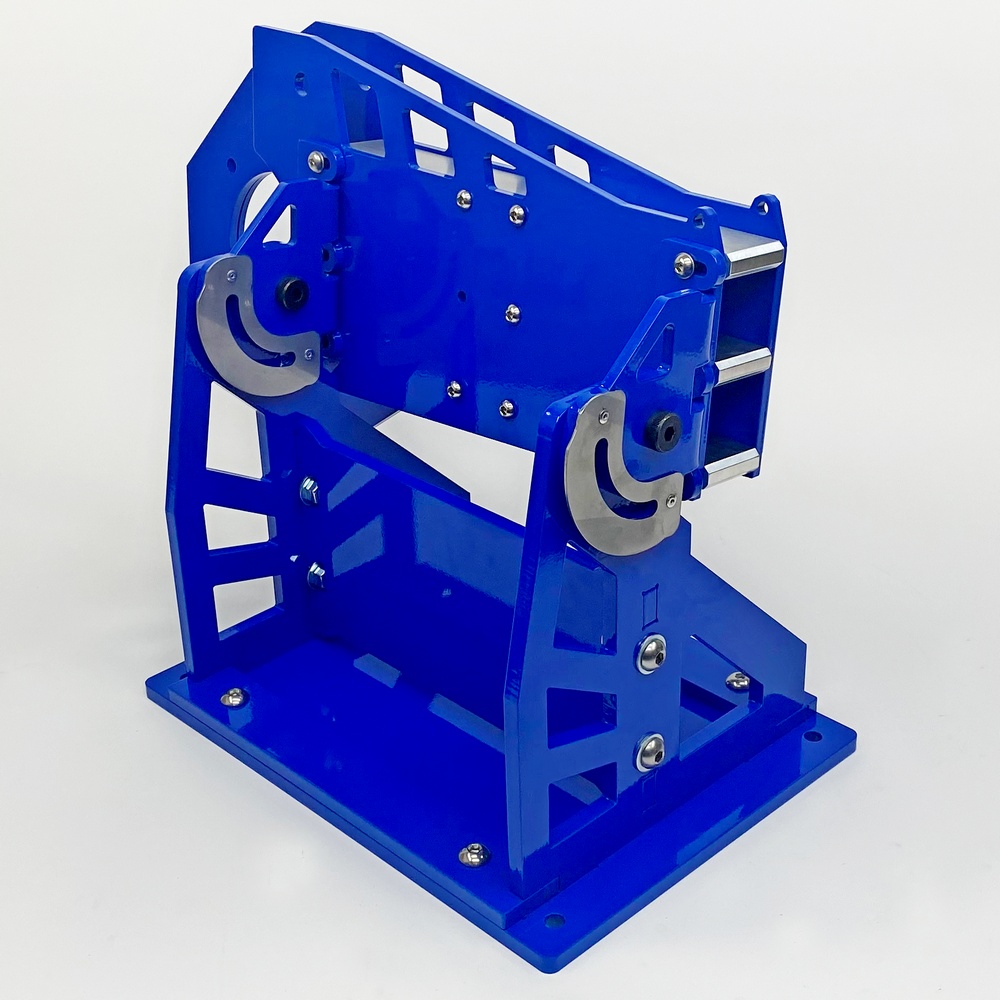
07.1 - Turn the Max Grinder right side up as pictured |
07.2 - Install the carriage bold into the upright square hole |
|
|
|
|
07.3 - Install the hardened washer from the other side |
07.4 - Install the Handle, repeat the steps for the other handle. Once done test the tilting feature to make sure it works well |
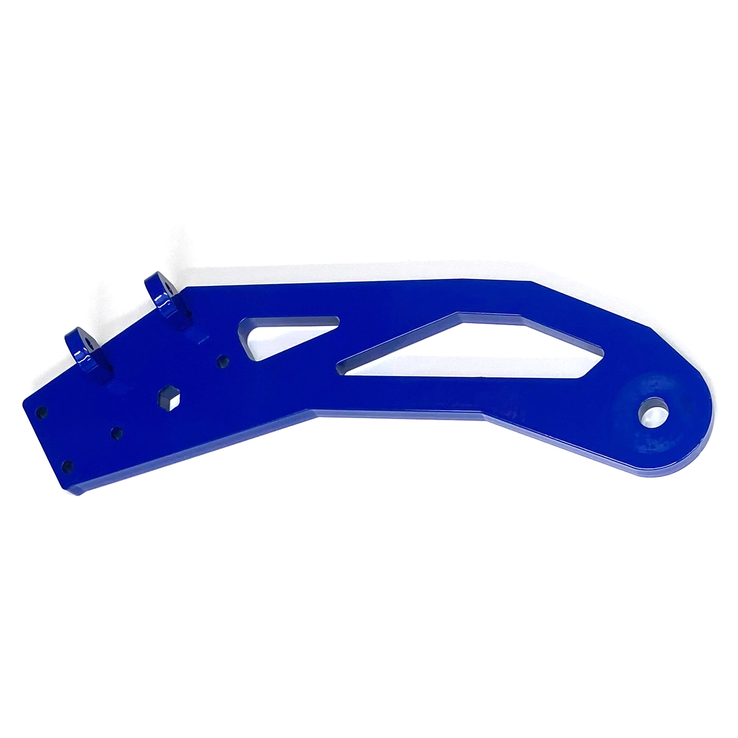
Step 8 - Tracking Arm Hinge
Bolt Kit 8
|
|
|
|
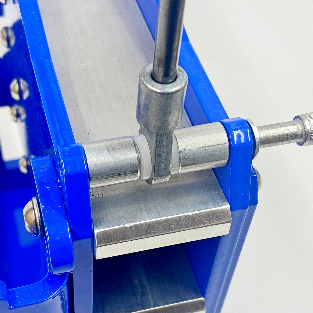
08.1 - Identify all the parts in Bolt Kit 8 |
08.2 - Insert the Nylon Washer and Space as pictured |
|
|
|
|
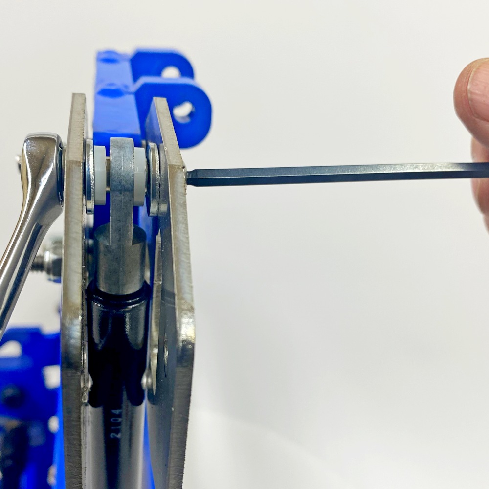
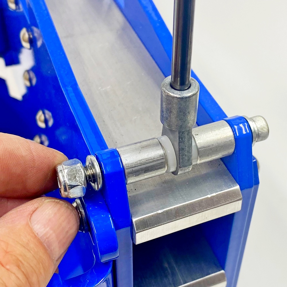
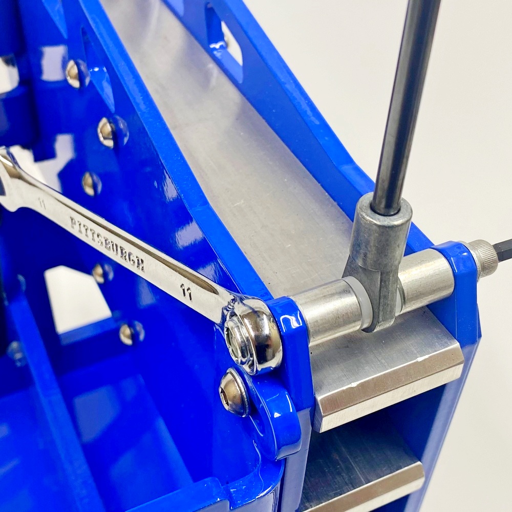
08.3 - The Tension ARM goes in the center between the two spacers |
08.4 - Tighten the bolt just enough so there is no movement but not too tight so the Tension Arm can’t move up and down |
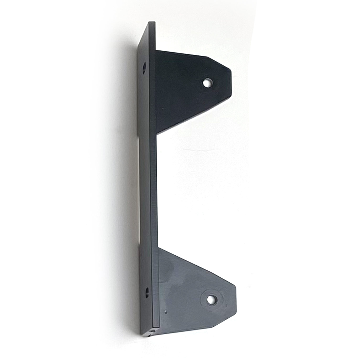
Step 9 - Gas Strut Side Plates
Bolt Kit 9
|
|
|
|
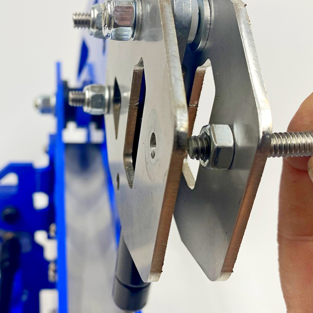
09.1 - Install the Tension Arm Side Plates |
09.2 - The two washers must go on the inside of the two side plates (see next picture) |
|
|
|
|
09.3 - The two larger washers must be mounted on the inside of the side plates, see pic 10.3 |
09.4 - Once done the grinder should look like the picture above |
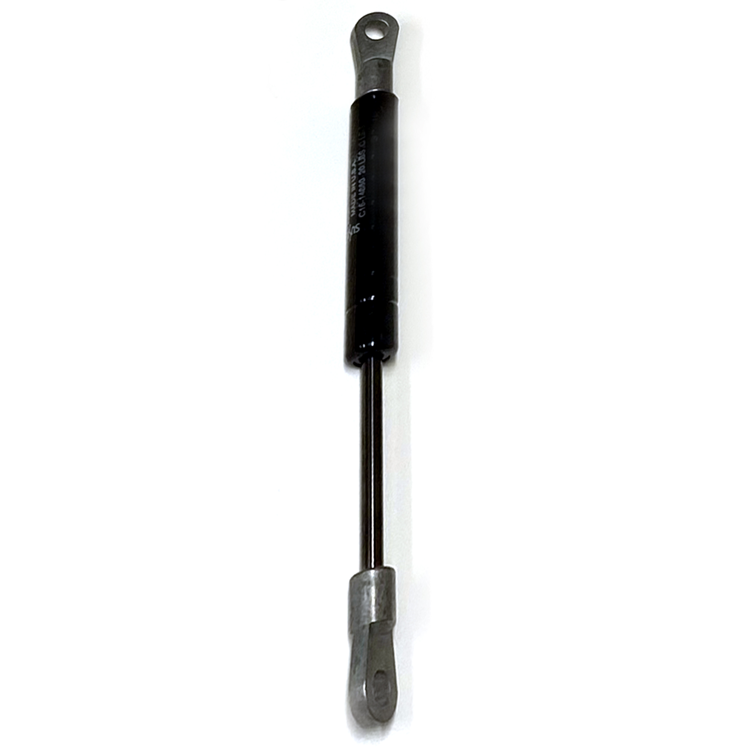
Step 10 - Gas Strut Installation Top
Bolt Kit 10
|
|
|
|
10.1 - Identify all the parts for the next step. Note the Gas Strut must be mounted upside down |
10.2 - Insert the bolt with washer as pictured in the picture above |
|
|
|
|
10.3 - Insert the metal spacer with the two Nylon washers on each side |
10.4 - The remaining washer goes on the end
|
|
|
|
|
10.5 - Insert the split washer and Nyloc Nut |
10.6 - Tighten the nut |
|
|
|
|
10.7 - Tighten the Nut, make sure there is enough clearance for the Gas Strut to move freely |
10.8 - Once done the side plates should look as pictured. Make sure the Gas Strut is UPSIDE DOWN |
Step 10b - Gas Strut Installation Bottom
Bolt Kit 10
|
|
|
|
10b.1 - Insert the bolt and washer as pictured |
10b.2 - Insert one metal spacer as pictured |
|
|
|
|
10b.3 - Insert the smaller metal spacer and one Nylon washer as pictured |
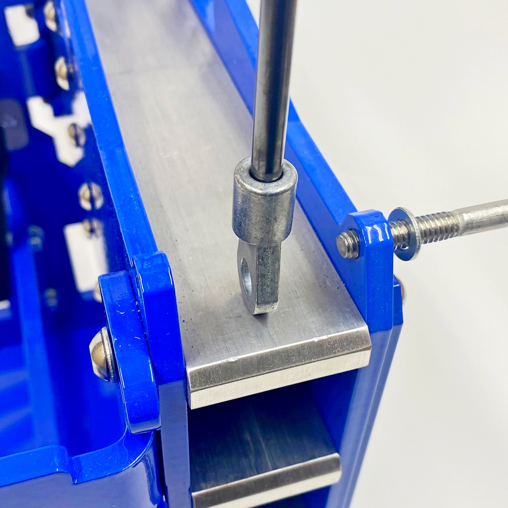
10b.4 - Insert the bottom eyelet over the spacer as pictured |
|
|
|
|
10b.5 - Insert the Nylo spacer as pictured |
10b.6 - Insert the metal spacer as pictured |
|
|
|
|
10b.7 - Insert the split washer and Nyloc Nut |
10b.8 - Tighten the Nyloc Nut |
Step 11 - Install the Control Arm Handle
Bolt Kit 11
|
|
|
|
11.1 - Insert the Bolt and Nut as pictured |
11.2 - Insert the remaining nut |
|
|
|
|
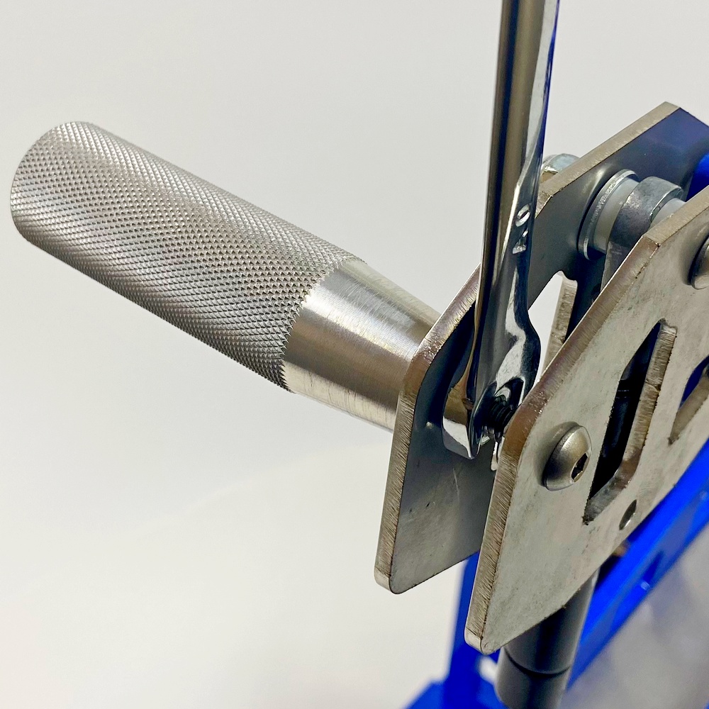
11.3 - Insert the Knurled Handle and tighten the Nut on the inside RIGHT |
11.4 - Screw in the Handle so it is just flush with the LEFT side plate. Tighten the Nut on the LEFT. |
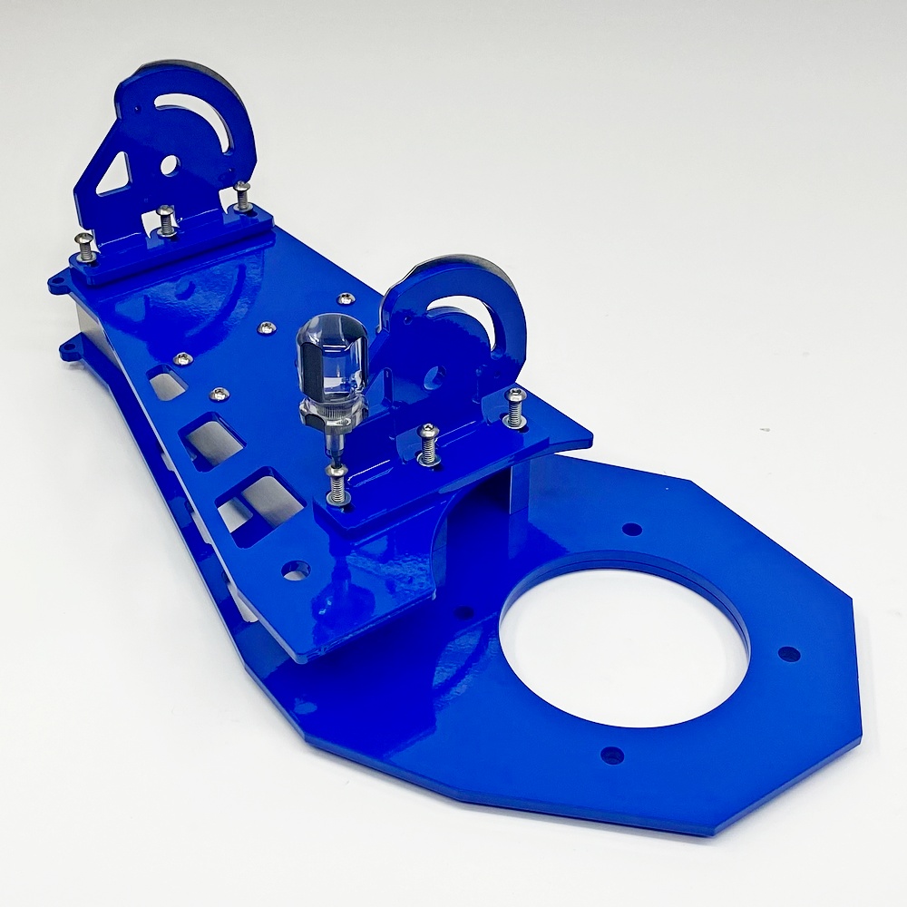
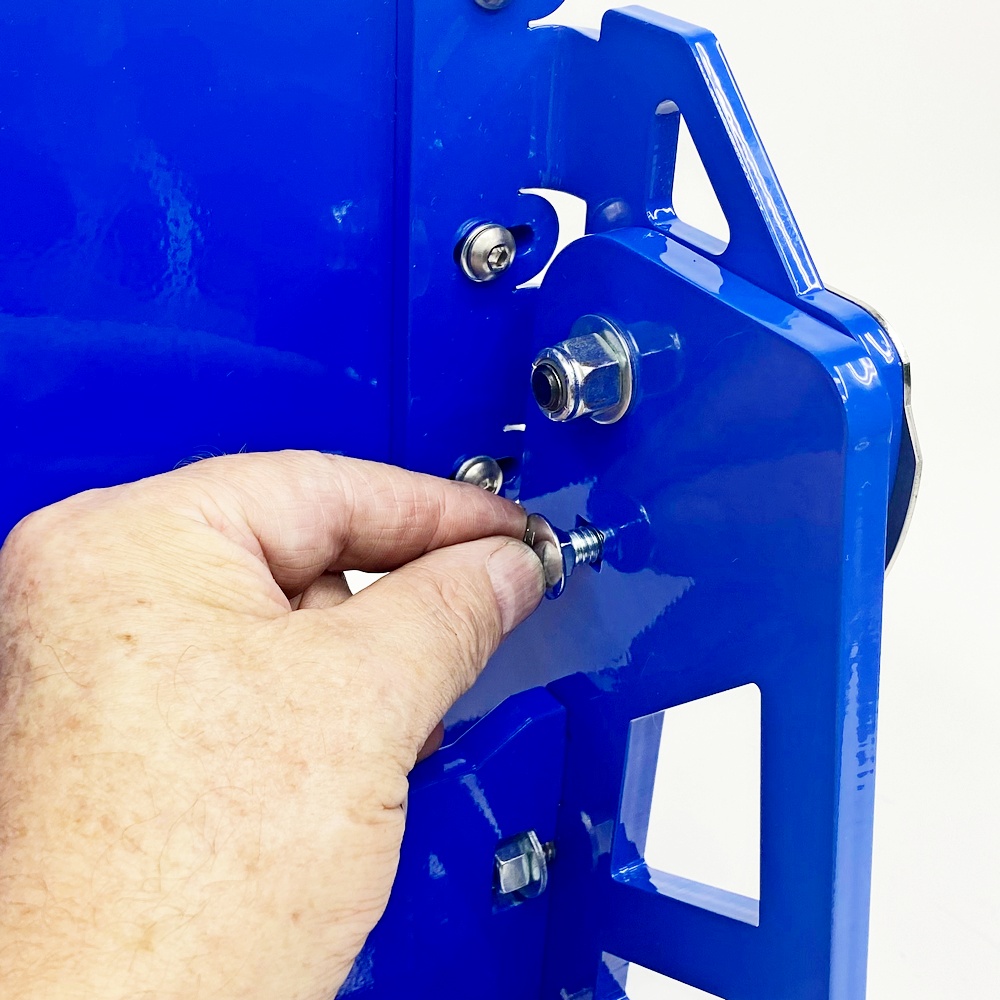
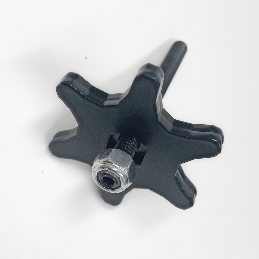
Step 12 - Install Tracking Wheel Adjusting Knob
Bolt Kit 12
|
|
|
|
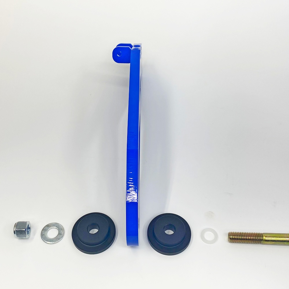
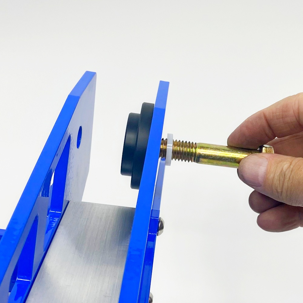
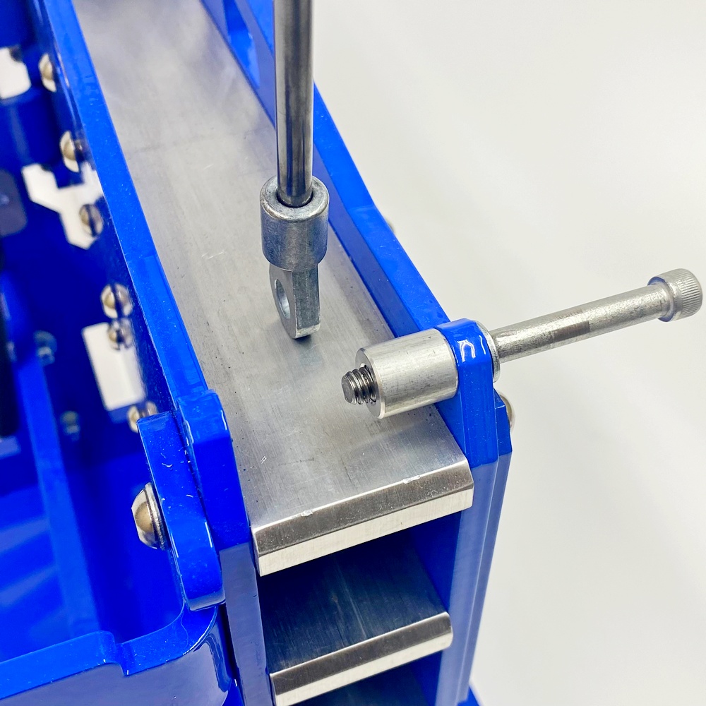
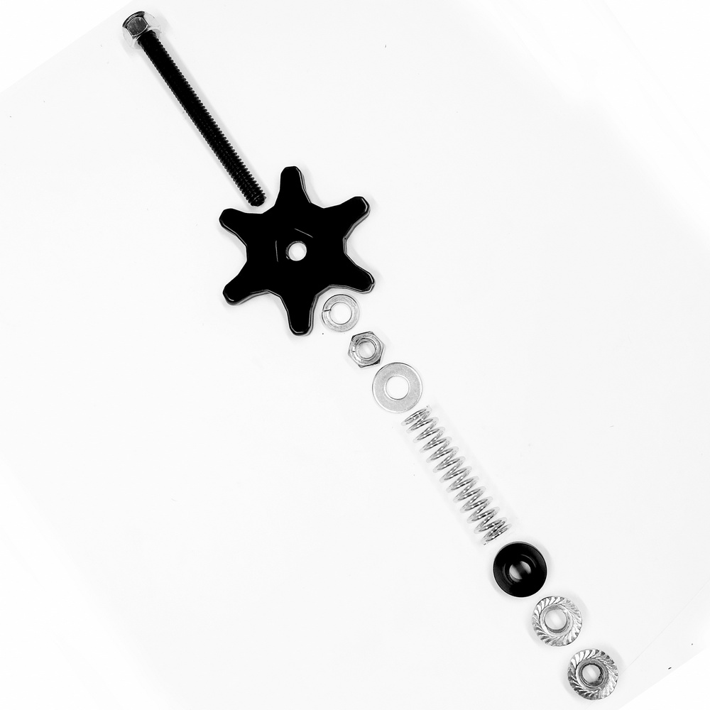
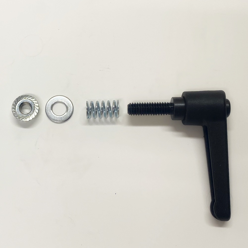
12.1 - Identify the parts |
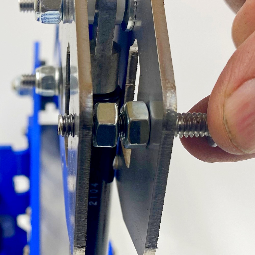
12.2 - Screw the Nyloc nut onto the Screwed Rod, TIP The screwed rod has an Allen Keyhole to hold it in place using an Allen wrench so it doesn’t turn while tightening the Nyloc Nut |
|
|
|
|
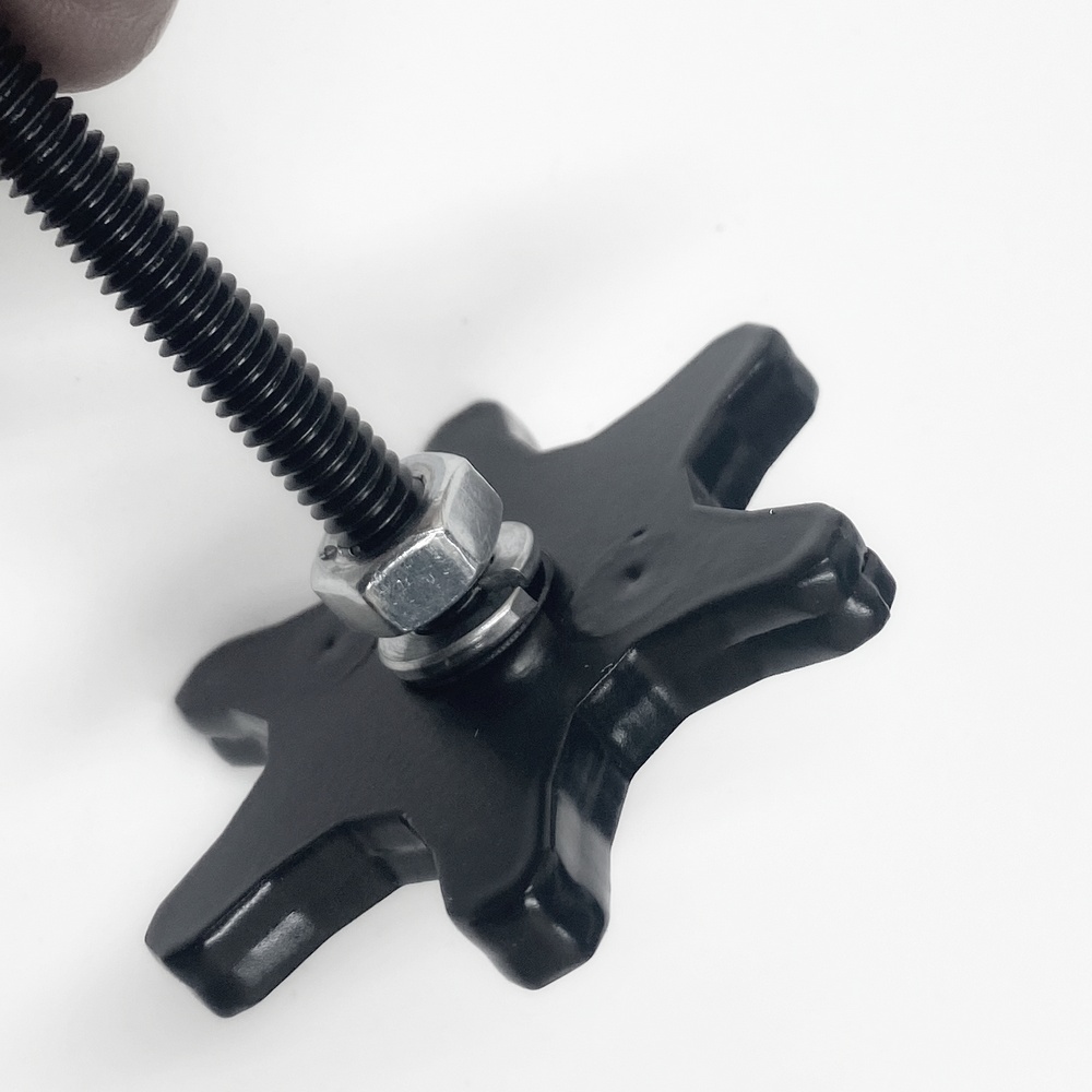
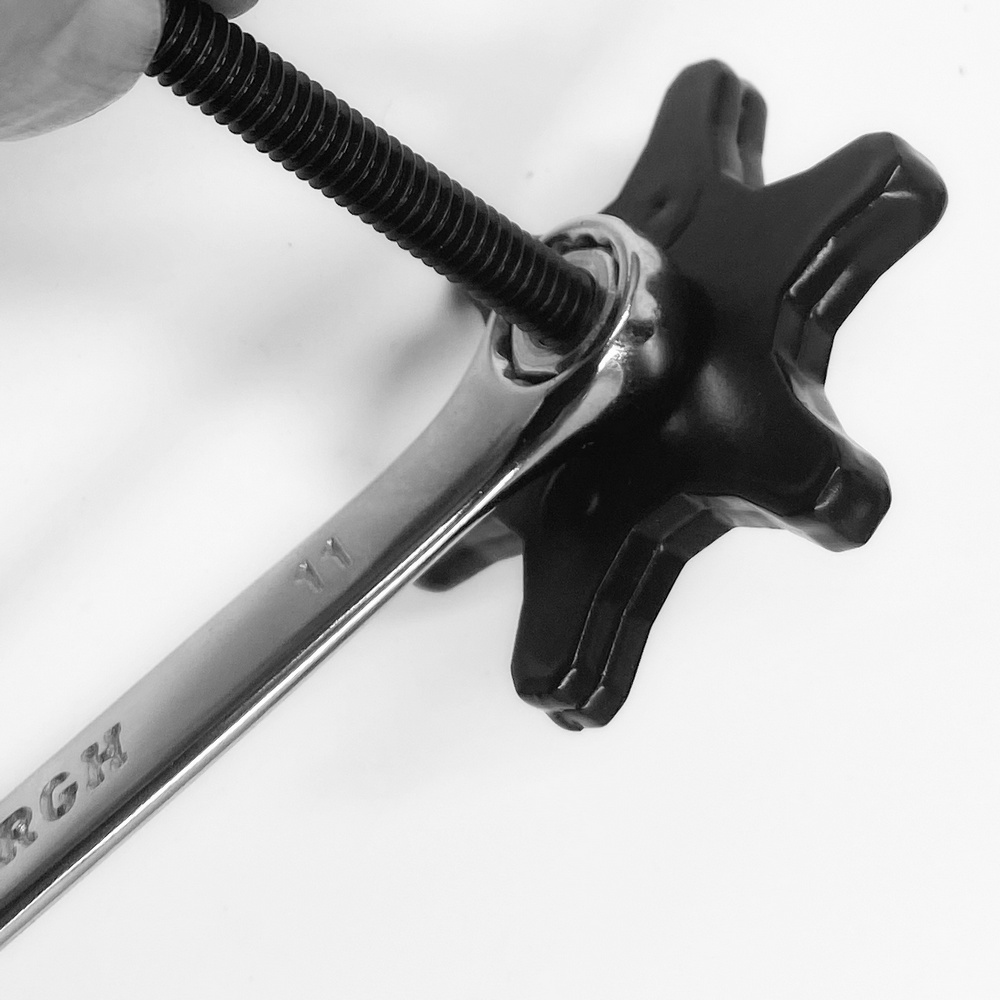
12.3 - From the other side add the split washer and regular nut |
12.4 - Tighten the two nuts to secure the screwed rod to the Knob. |
|
|
|
|
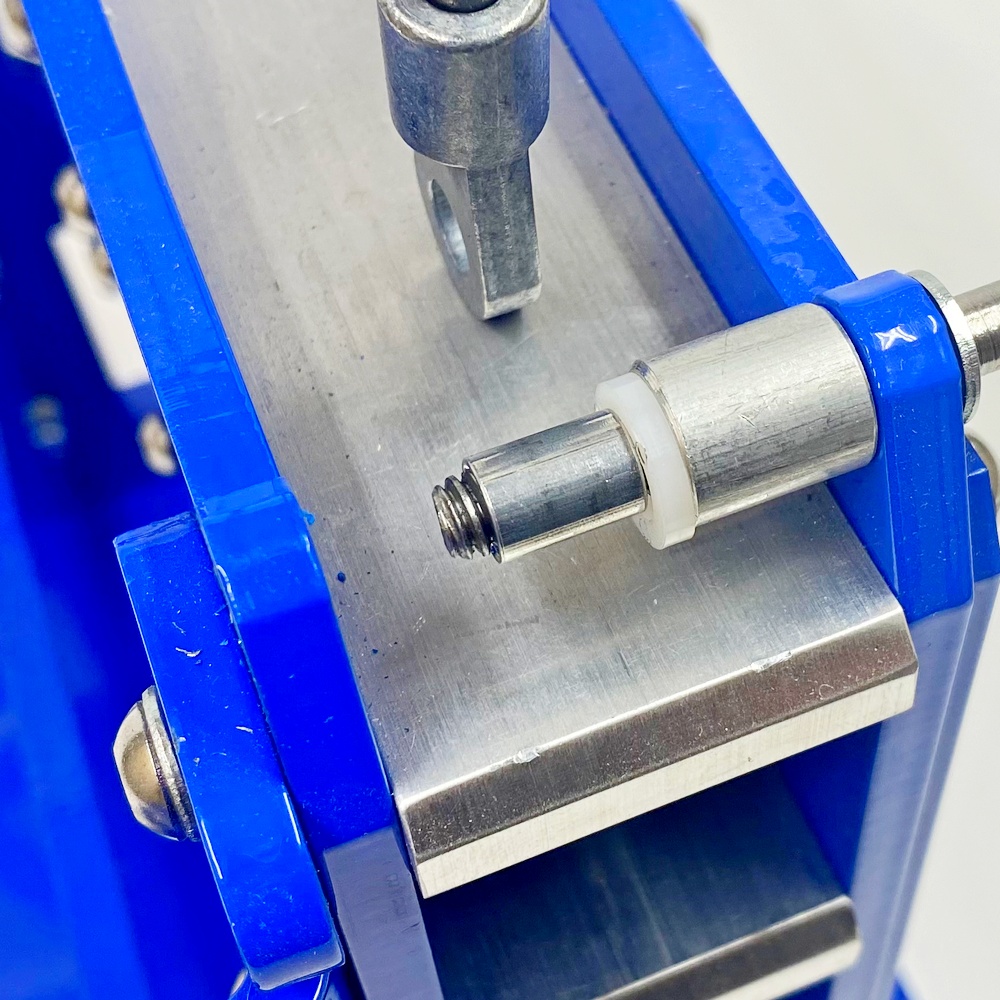
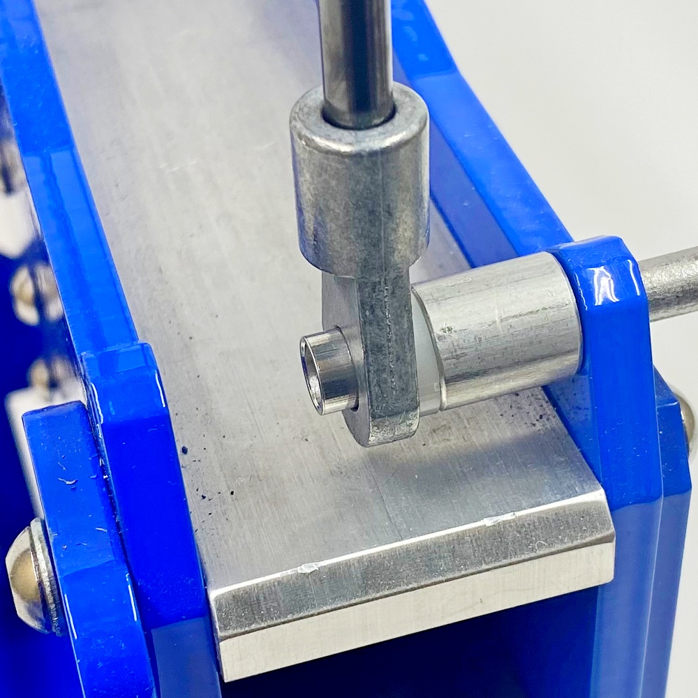
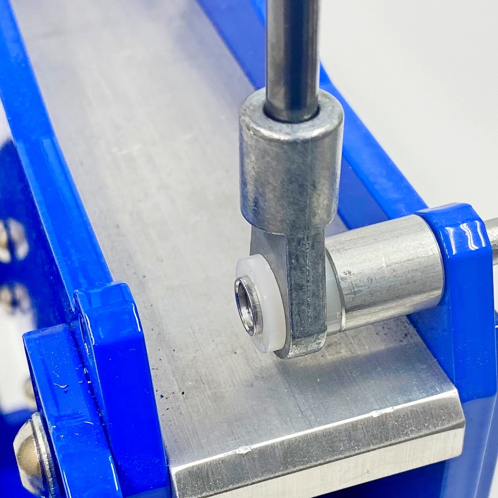
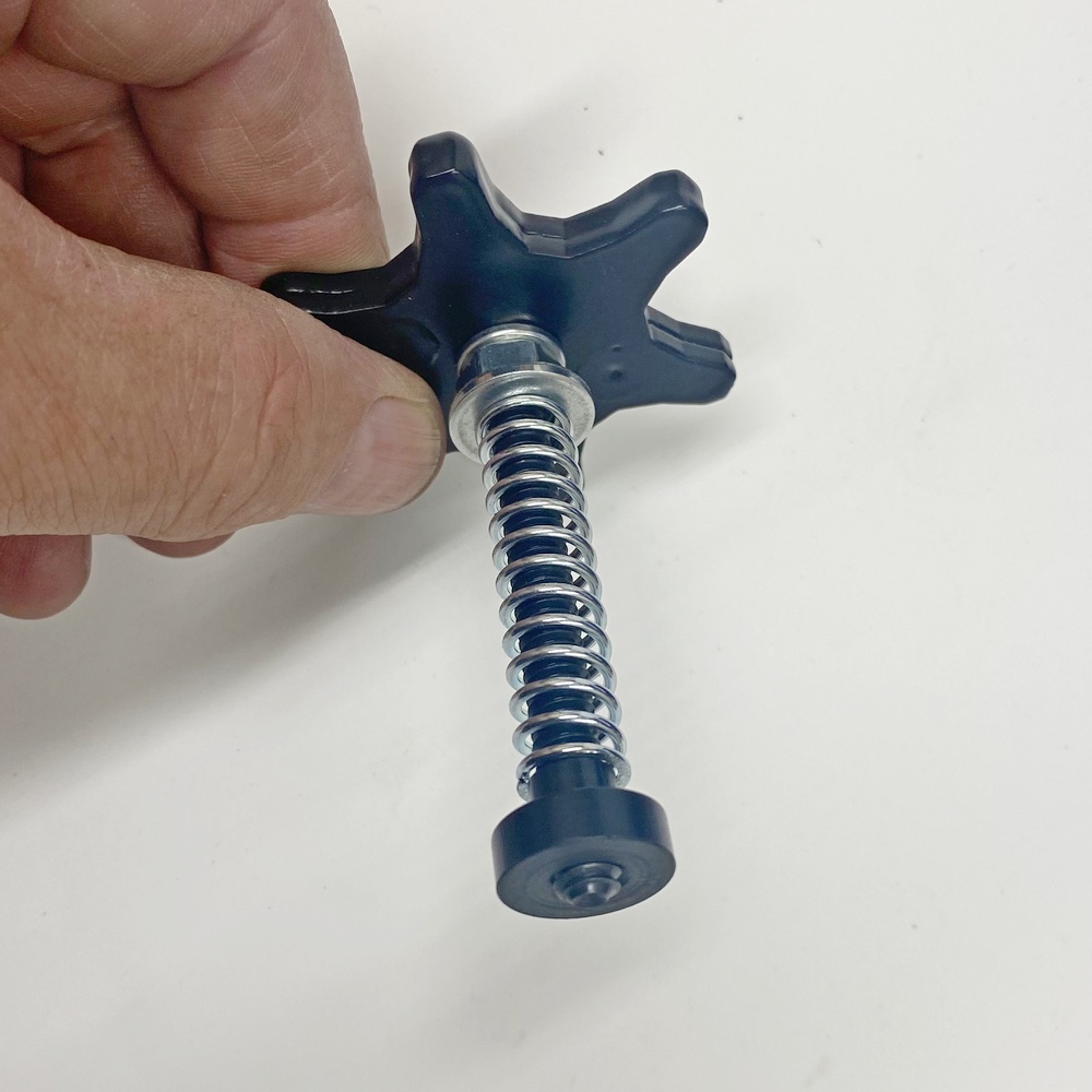
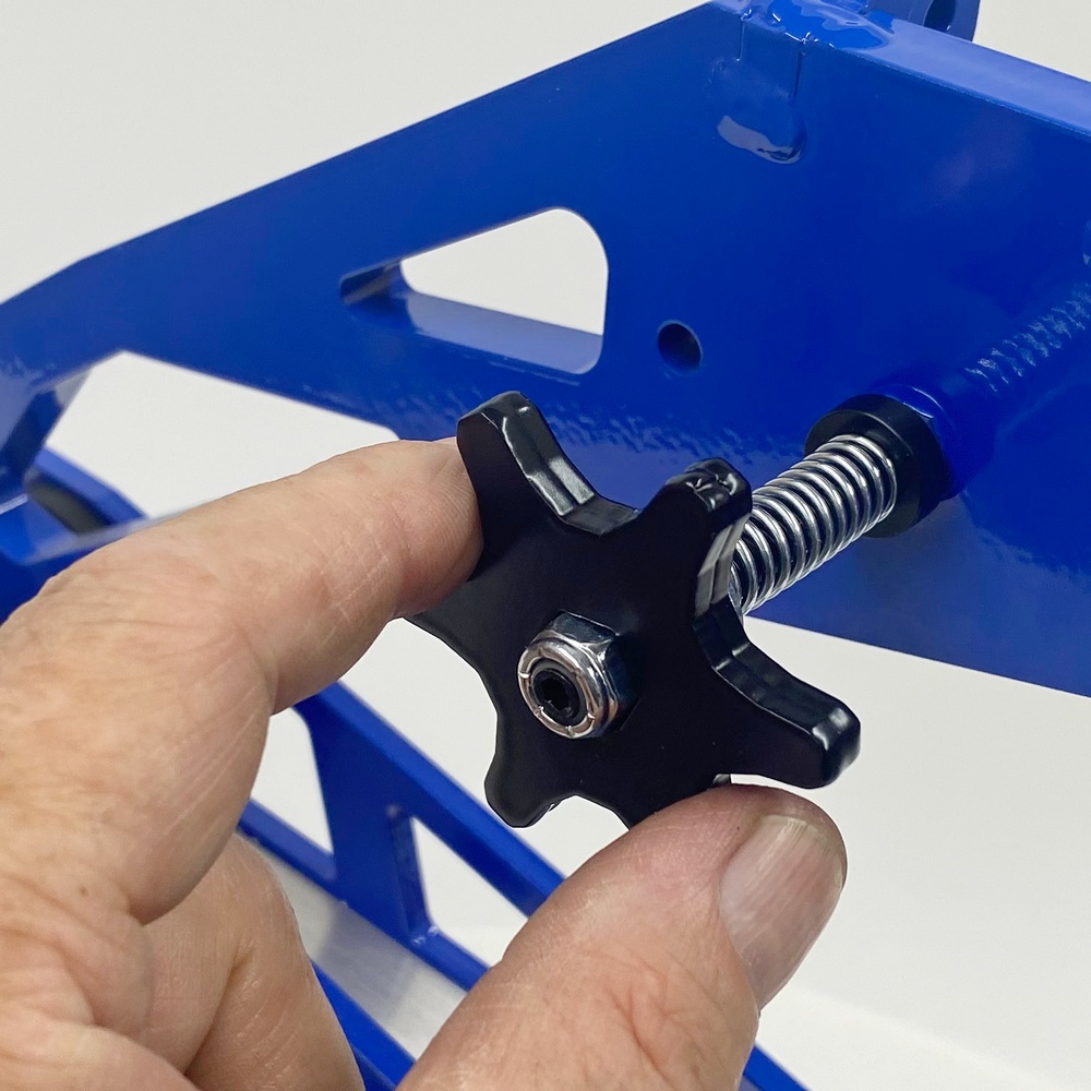
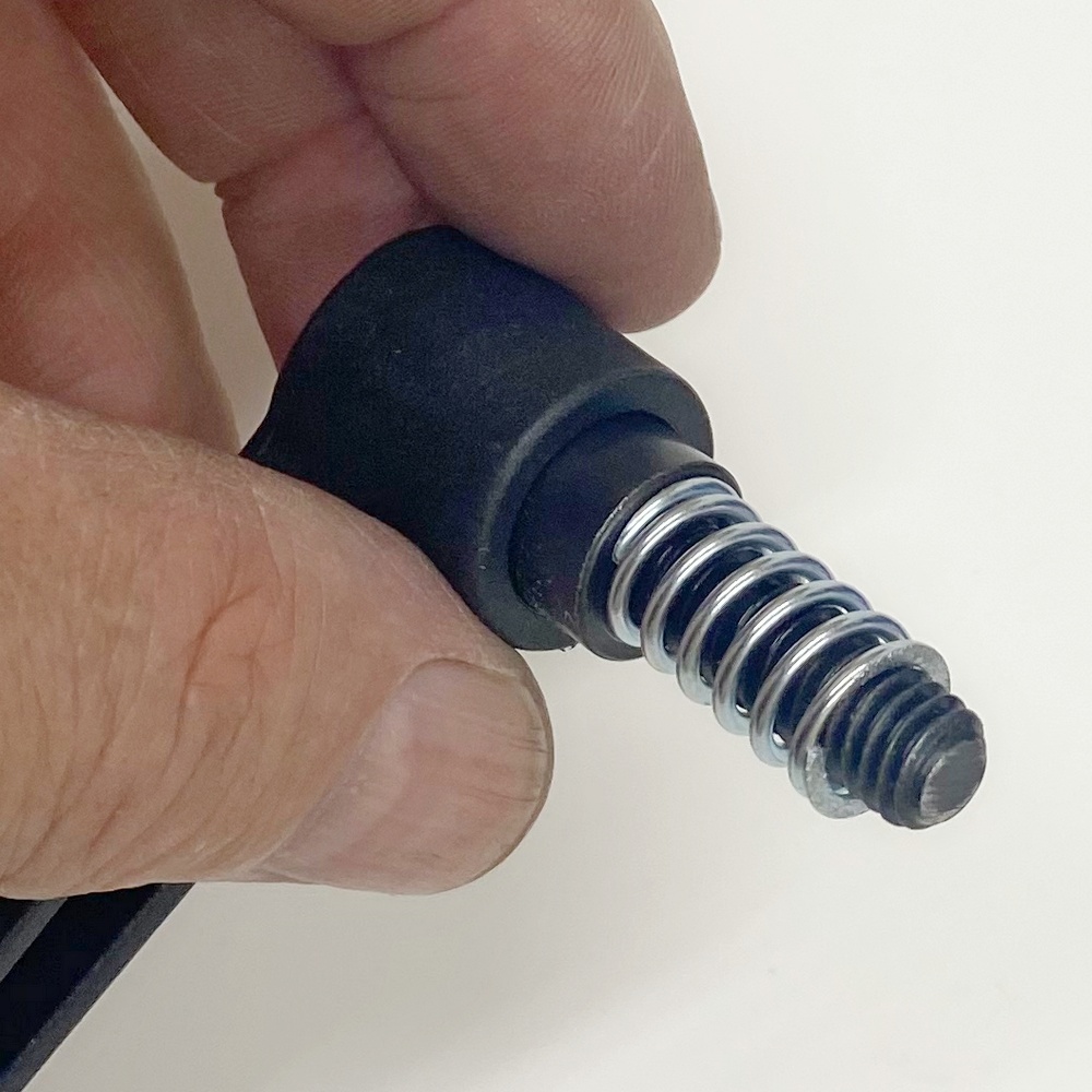
12.5 - Next add the Washer, Spring, and Spacer as pictured. Set the knob aside for use after the next step. |
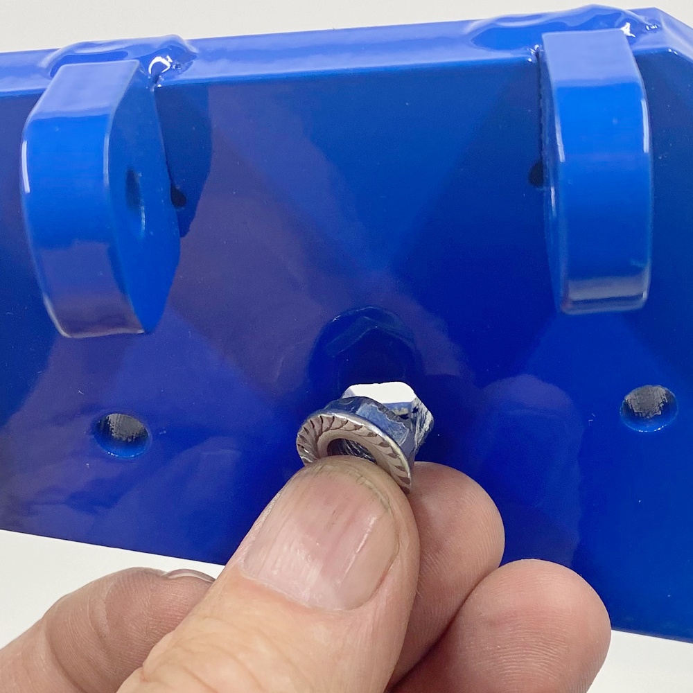
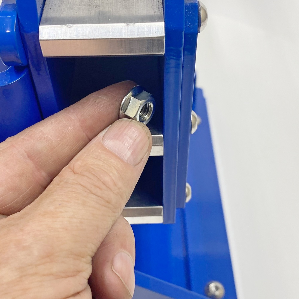
12.6 - Insert the NUT into the hole as pictured, if the nut is too tight you can use a C-Clamp to press it into place NOTE: This step might already be completed at the factory |
|
|
|
|
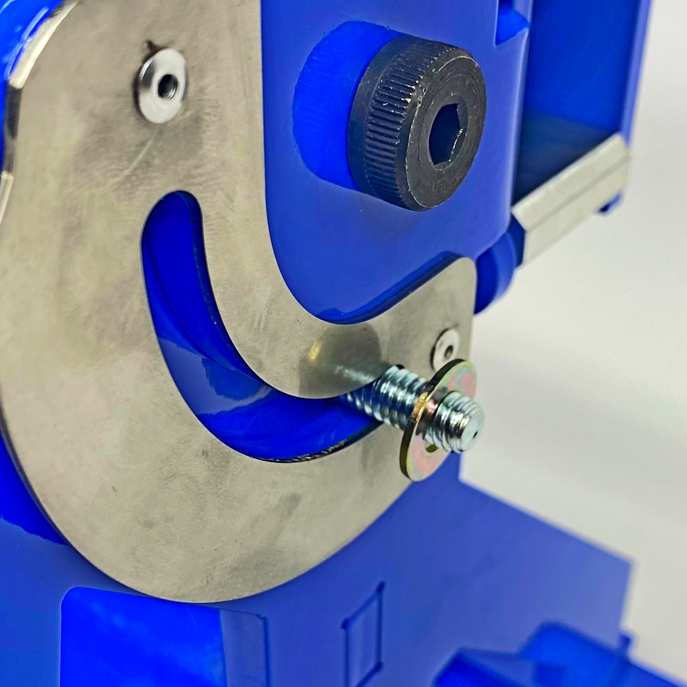
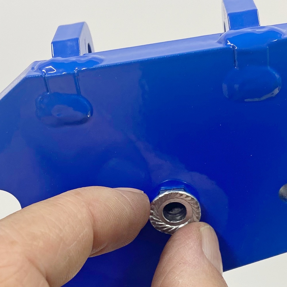
12.7 - Working from the other side insert the NUT. IMPORTANT! - THIS NUT SHOULD BE BORED OUT SO THE ROD CAN PASS THROUGH THE HOLE |
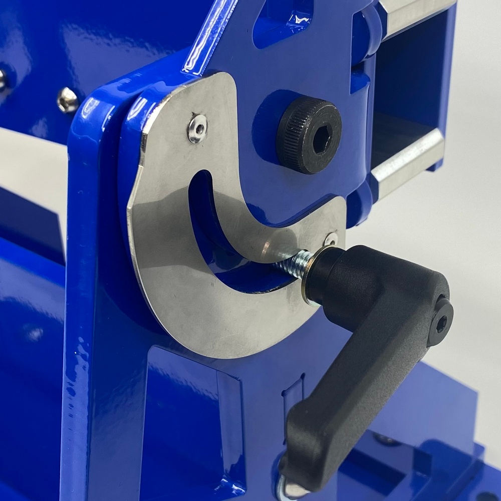
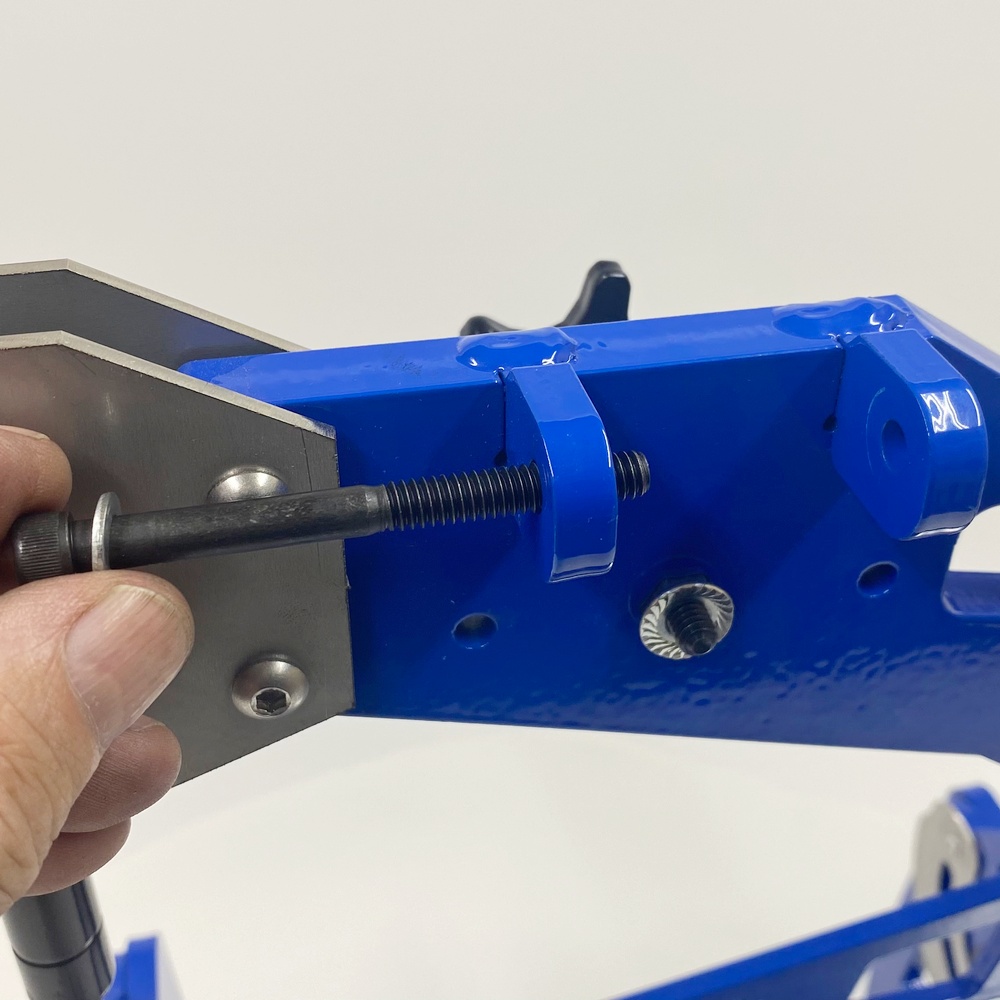
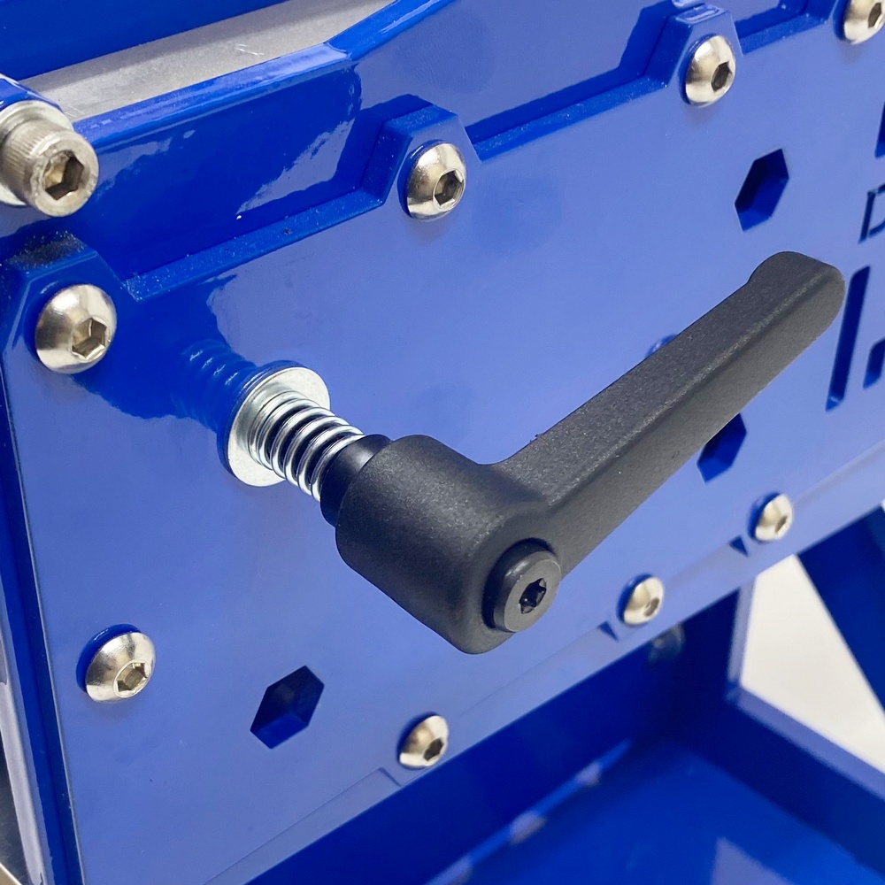
12.8 - Screw the knob assembly into the hole |
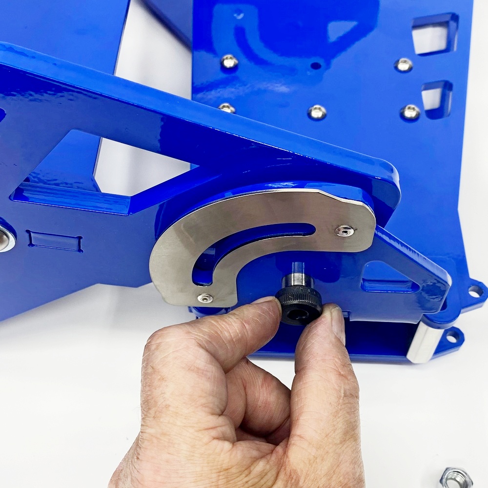
Step 13 - Install Tracking Wheel Adjusting Knob
Bolt Kit 13
|
|
|
|
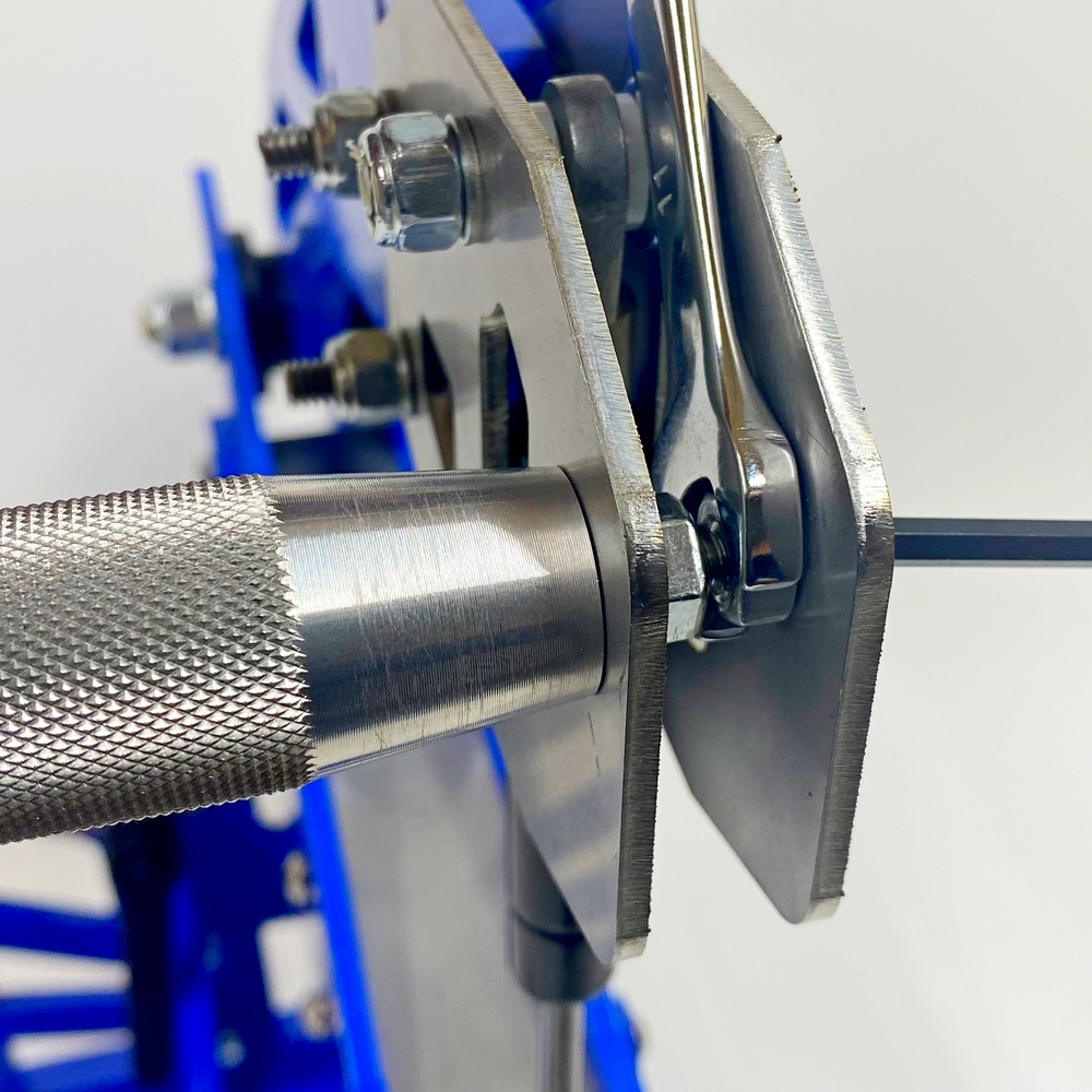
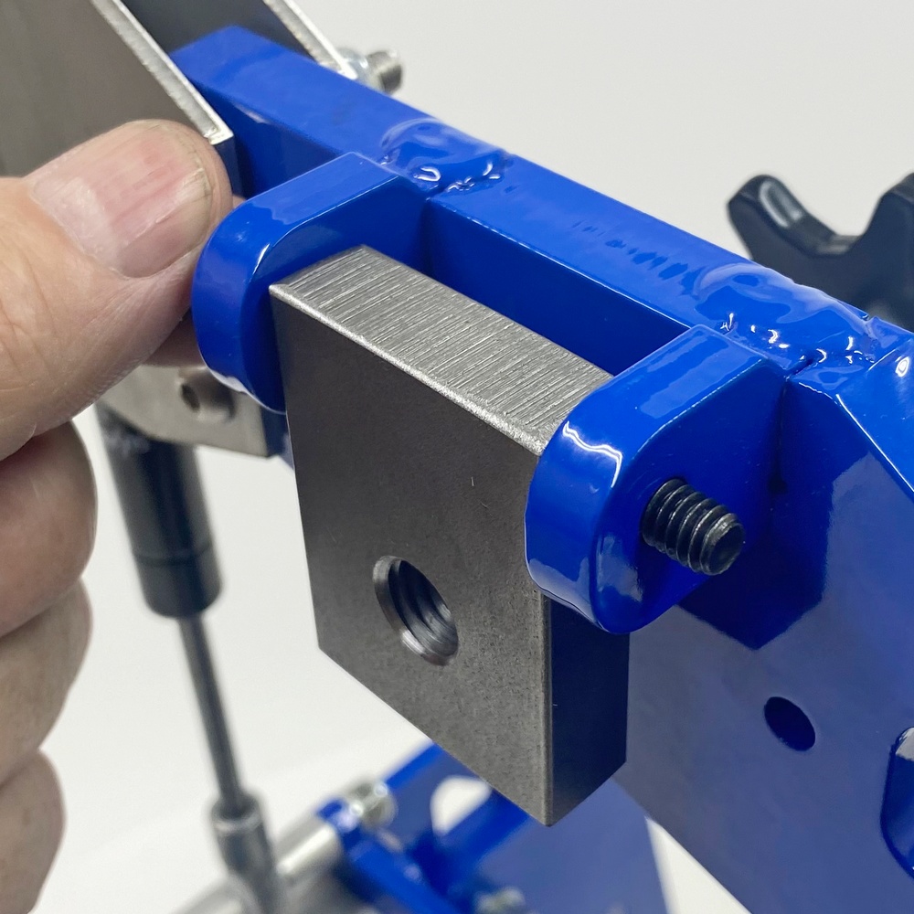
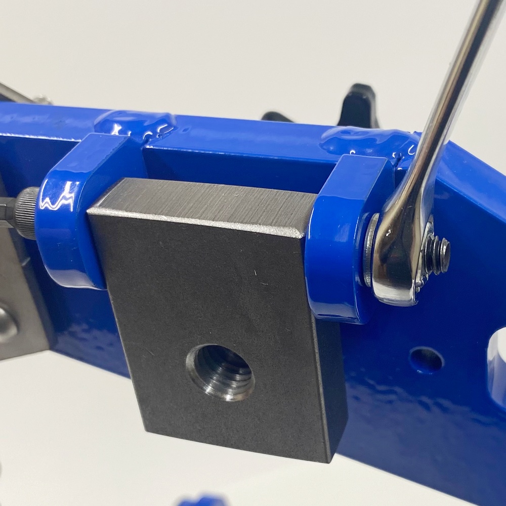
13.1 - Insert the Allen Bolt with Washer as pictures |
13.2 - Slide the tracking block in place |
|
|
|
|
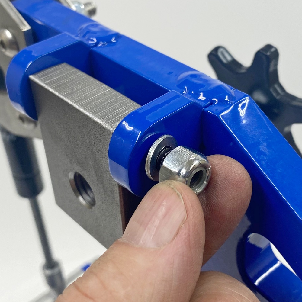
13.3 - Insert the Nyloc Nut and Washer as pictured |
13.4 - Tighten the Nut, make sure the block can move freely |
Step 14 - Assemble and Attach the Tracking Wheel
Bolt Kit 14
|
|
|
|
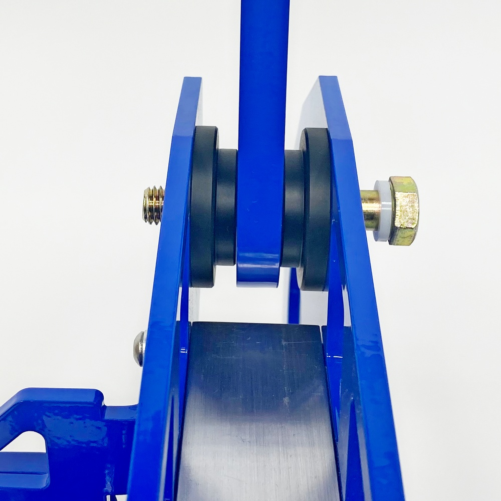
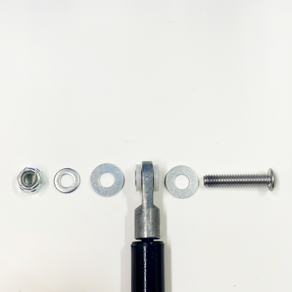
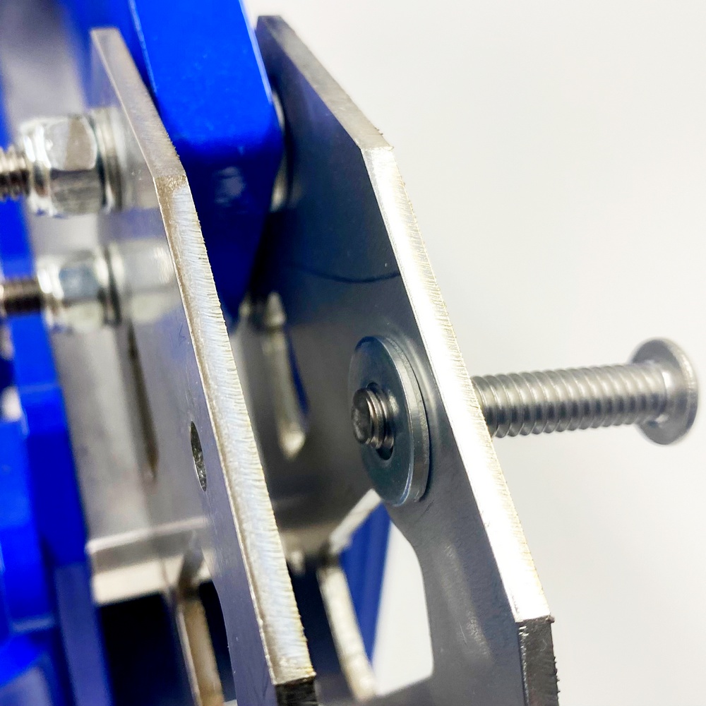
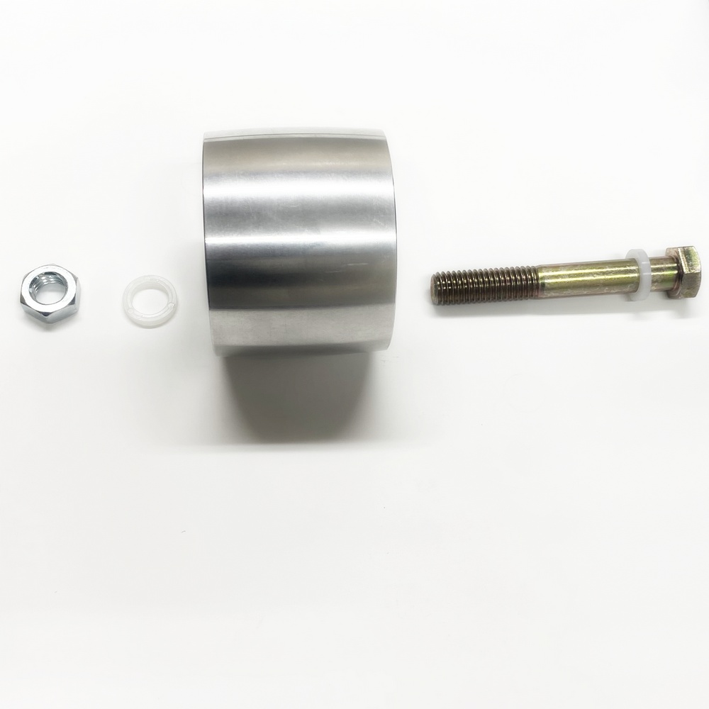
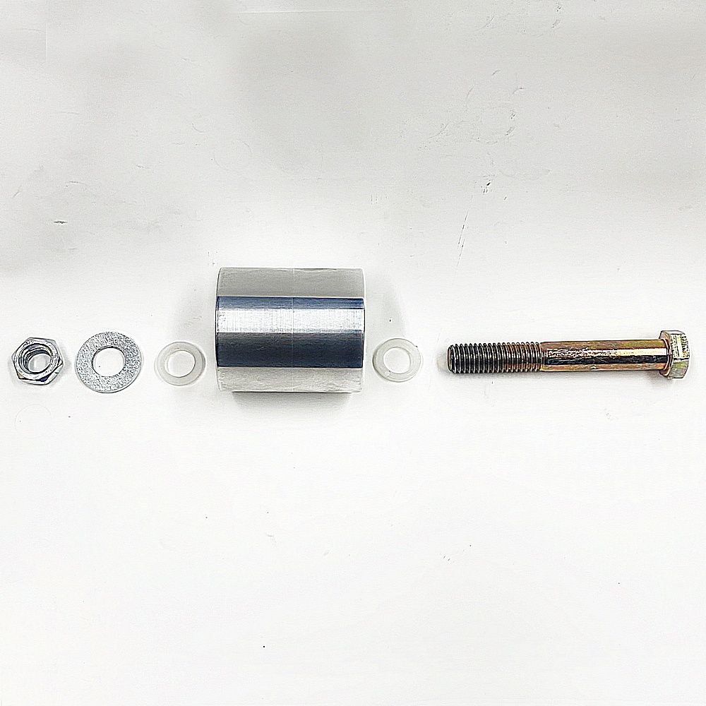
14.1 - Identify the parts, Bolt, Nylon Washer, Tracking Wheel, Nylon Washer, Nut |
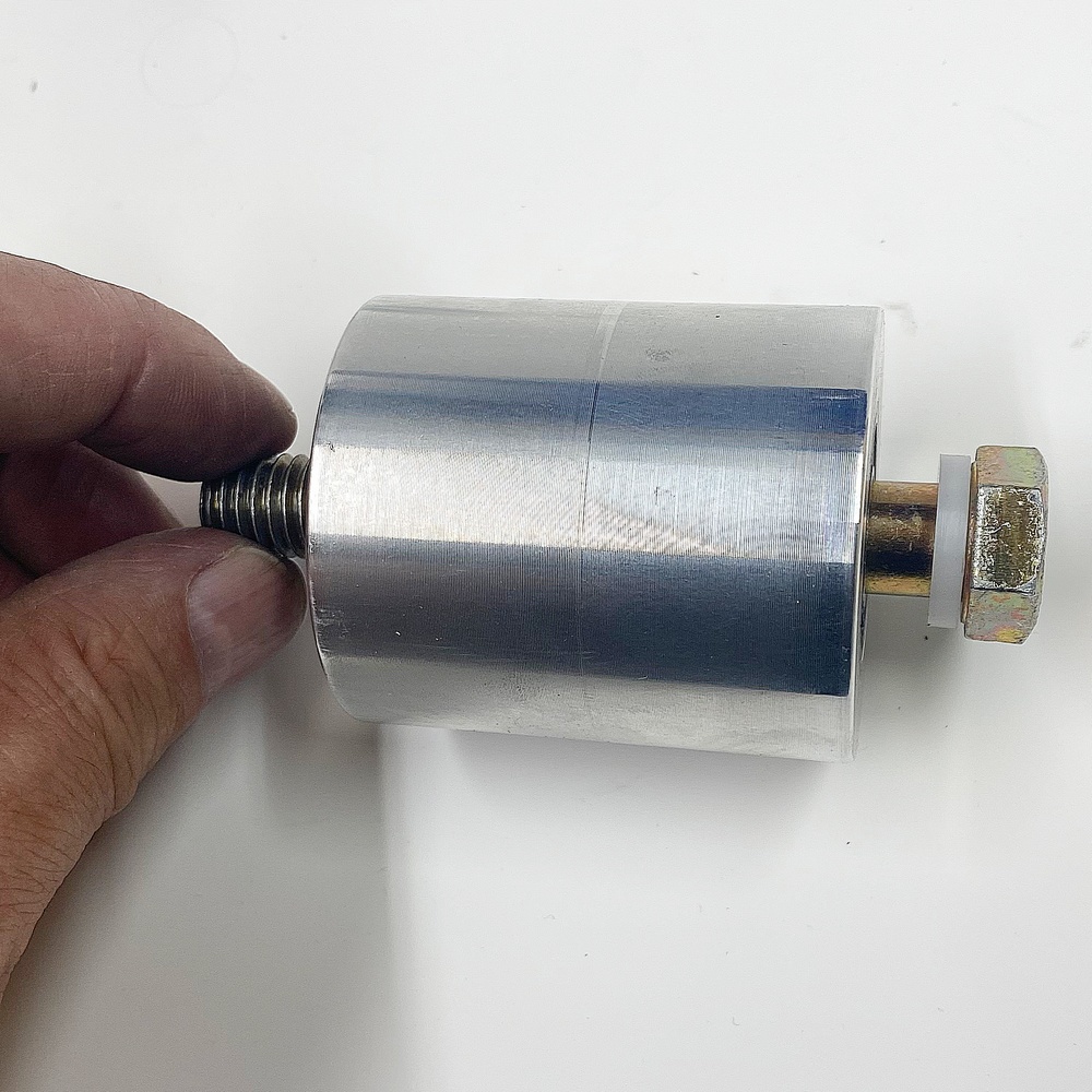
14.2 - Inset a Nylon Washer into the bolt and insert the bolt into the Tracking Wheel as pictured |
|
|
|
|
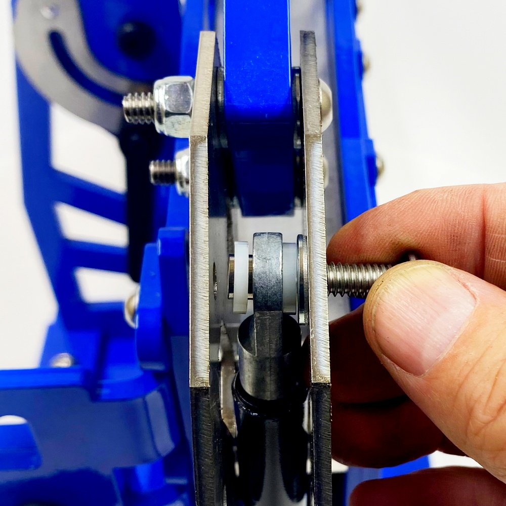
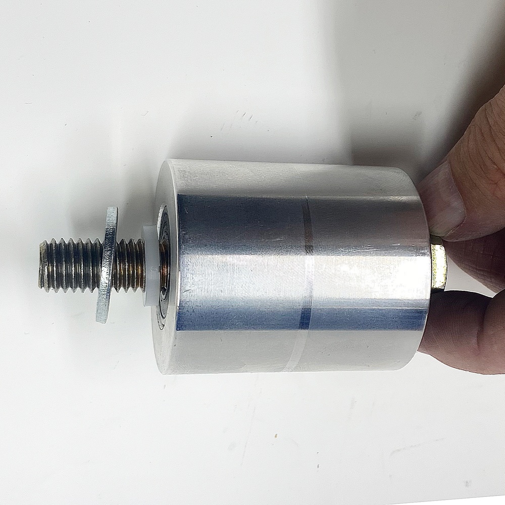
14.3 - From the other side add another Nylon Washer and Nut |
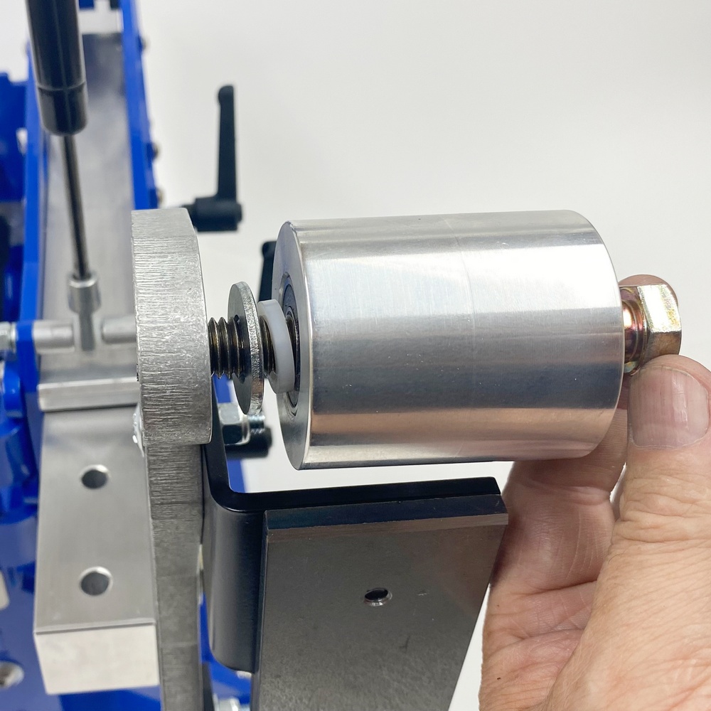
14.4 - Screw the Axle Bolt into the Tracking Block |
|
|
|
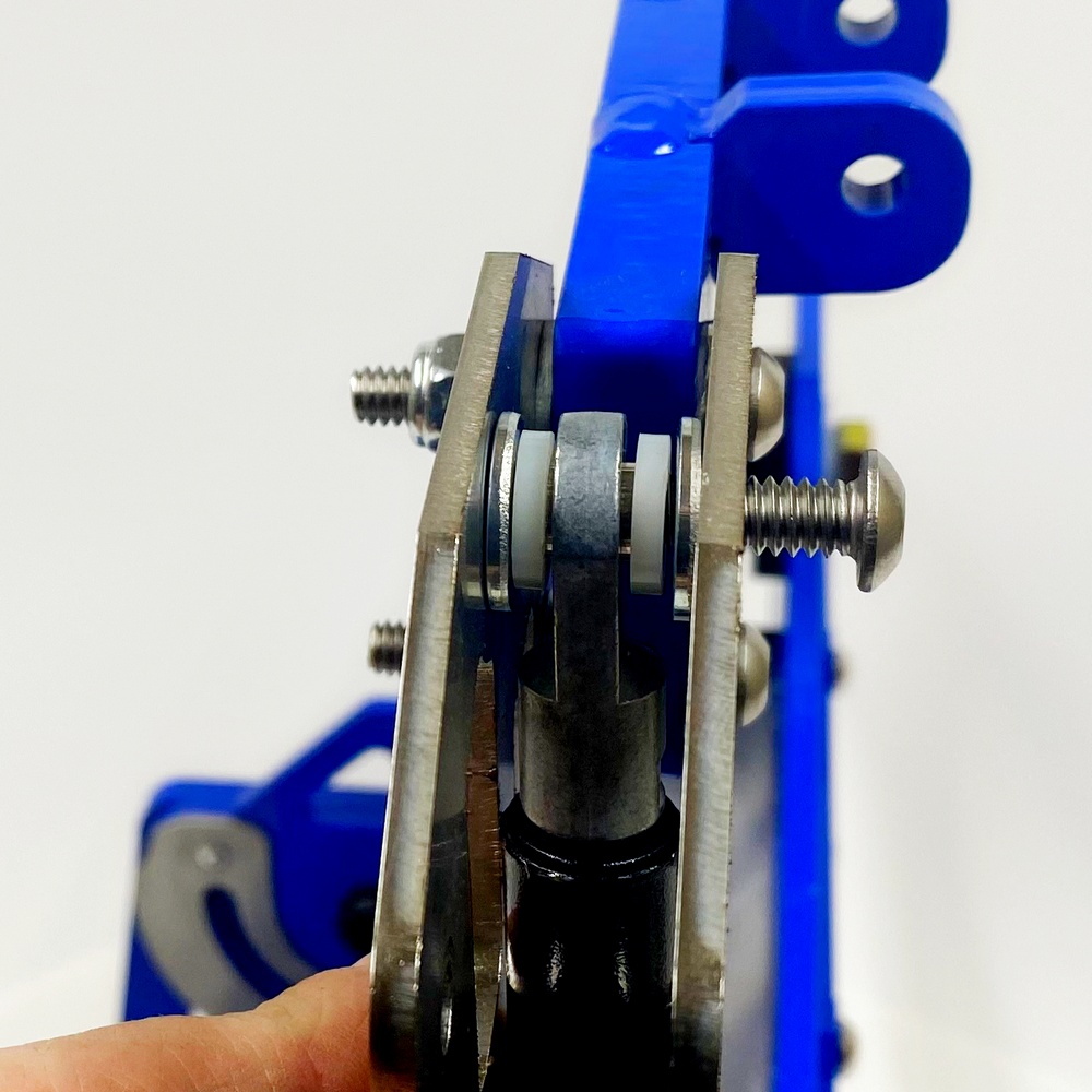
14.5 - Tighten the NUT.
IMPORTANT! - Make sure that the wheel spins freely, if the wheel is too tight then loosen the NUT and back out the bolt, then re-tighten the nut. |
Step 15 - Install the Tooling Arm and Handles
Bolt Kit 15
|
|
|
|
15.1 - Identify the Parts and order of assembly |
15.2 - Insert the Spring and Washer |
|
|
|
|
15.3 - Insert the NUT from inside the Tooling Arm receiver |
15.4 - Next, screw in the Assembled Handle as pictured |
|
|
|
|
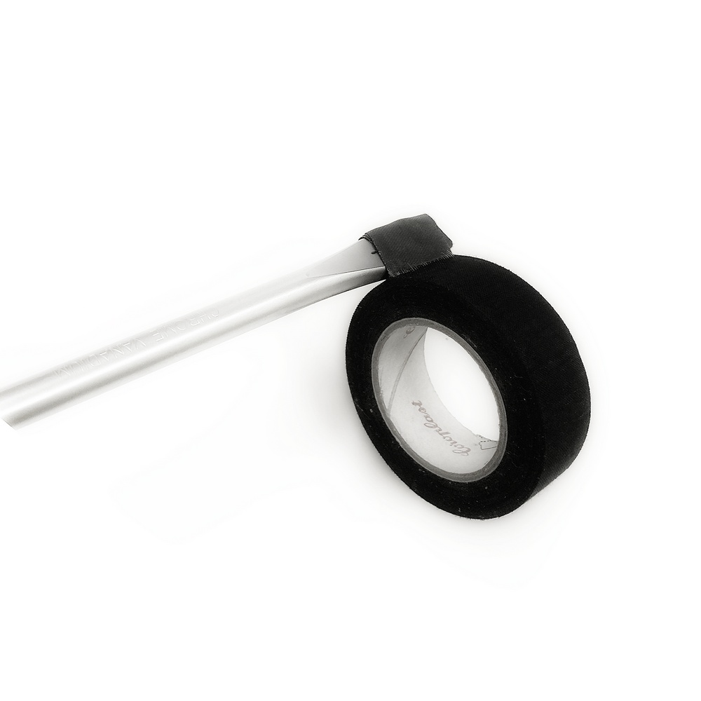
15.5 - Using a long screwdriver, wrap electrical tape, sticky side out around the tip |
15.6 - With the sticky tip add the NUT and insert it into the tooling ARM Receiver socket, as illustrated in the next image |
|
|
|
|
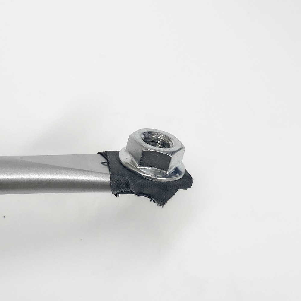
15.7 - Insert the NUT using the sticky screwdriver tip |
15.8 - Attach the handle to the NUT, the same as before |

|
|
|
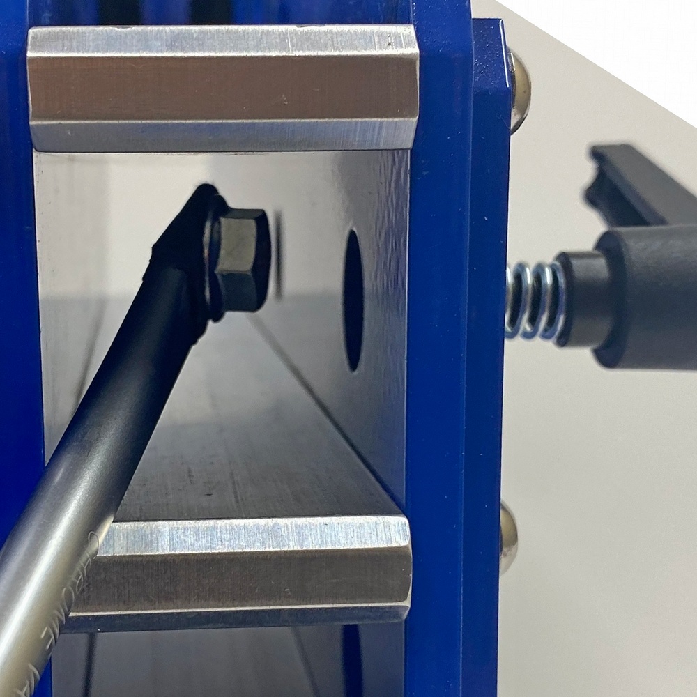
15.9 - Insert the Tooling Arm with the Threaded Holes as pictured |
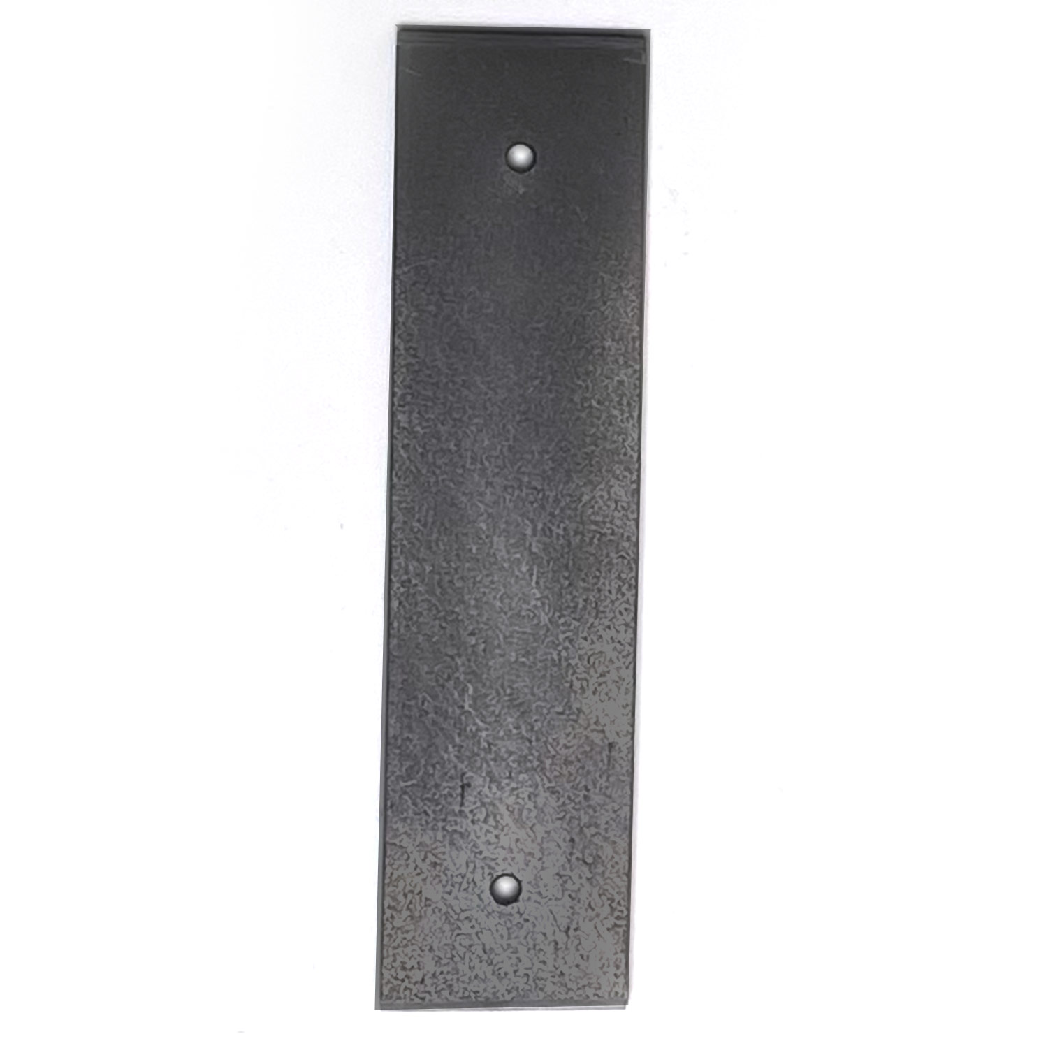
Step 16 - Install the D-Plate
Bolt Kit 16
|
|
|
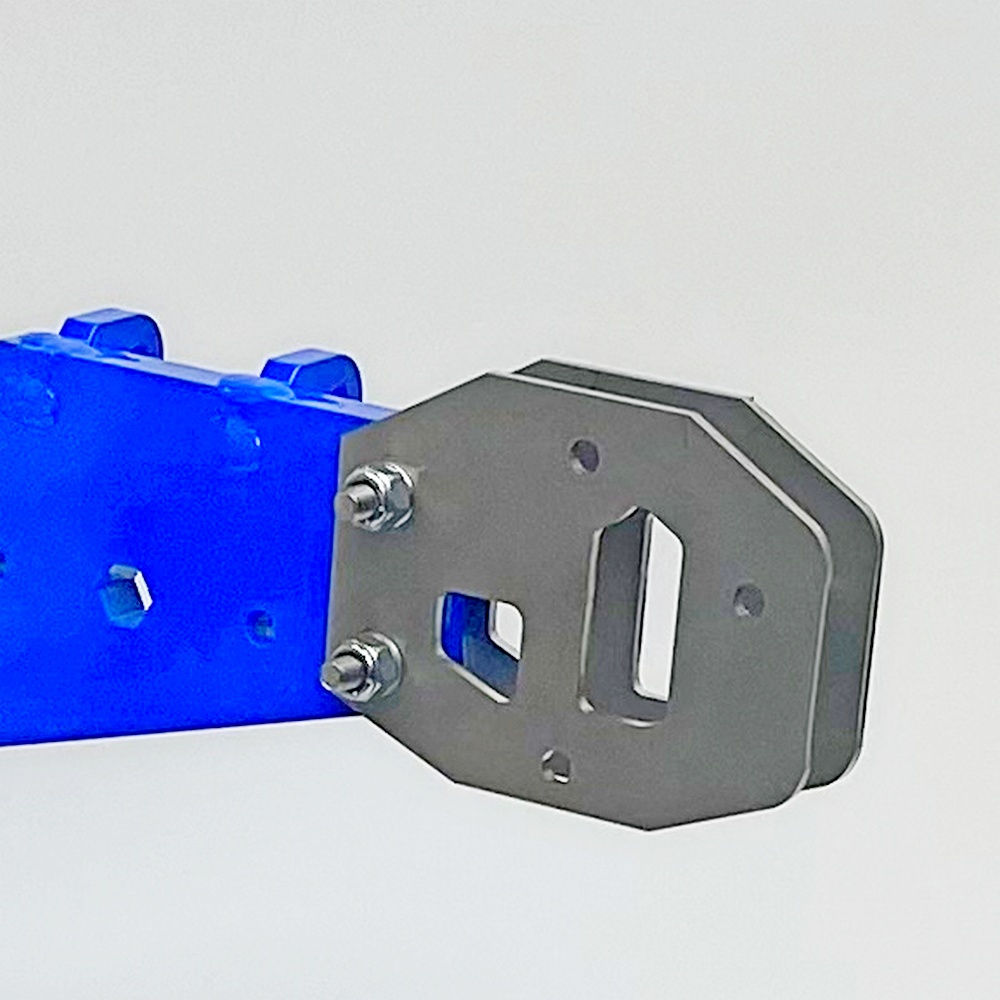
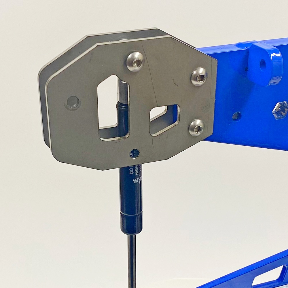
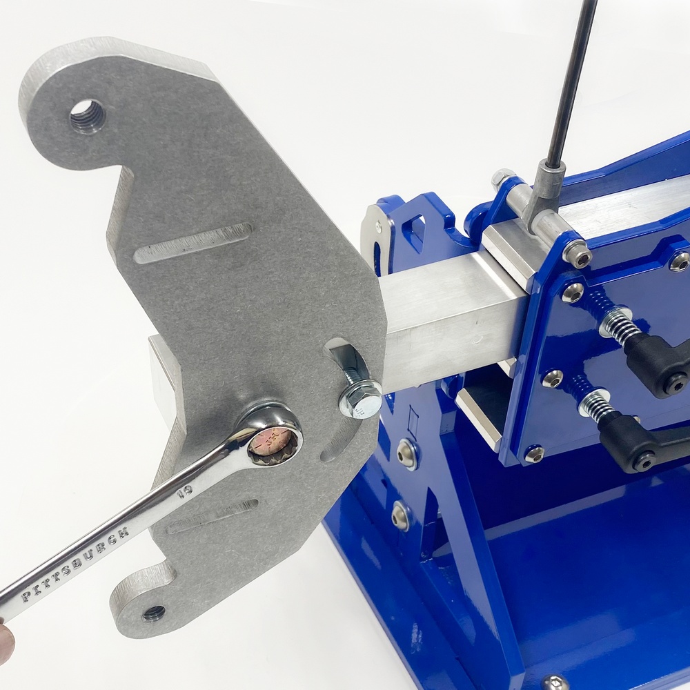
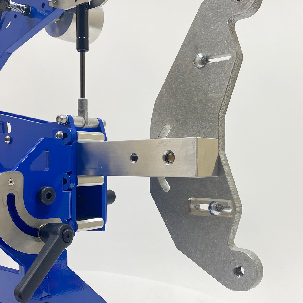
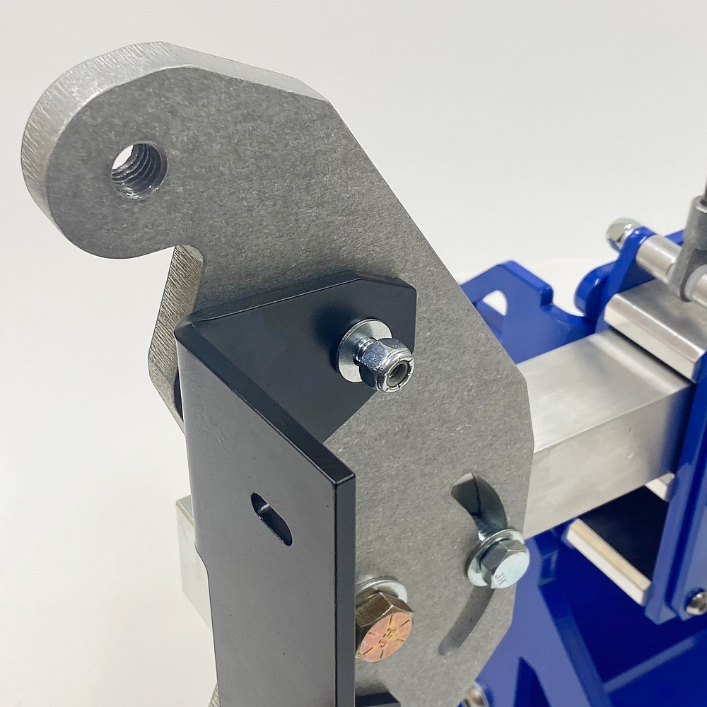
16.1 - Install the D-Plate as pictures |
Step 17 - Install the Platen Bracket
Bolt Kit 17
|
|
|
|
17.1 - Identify the Parts |
17.2 - Install the carriage bolts from the back as pictured |
|
|
|
|
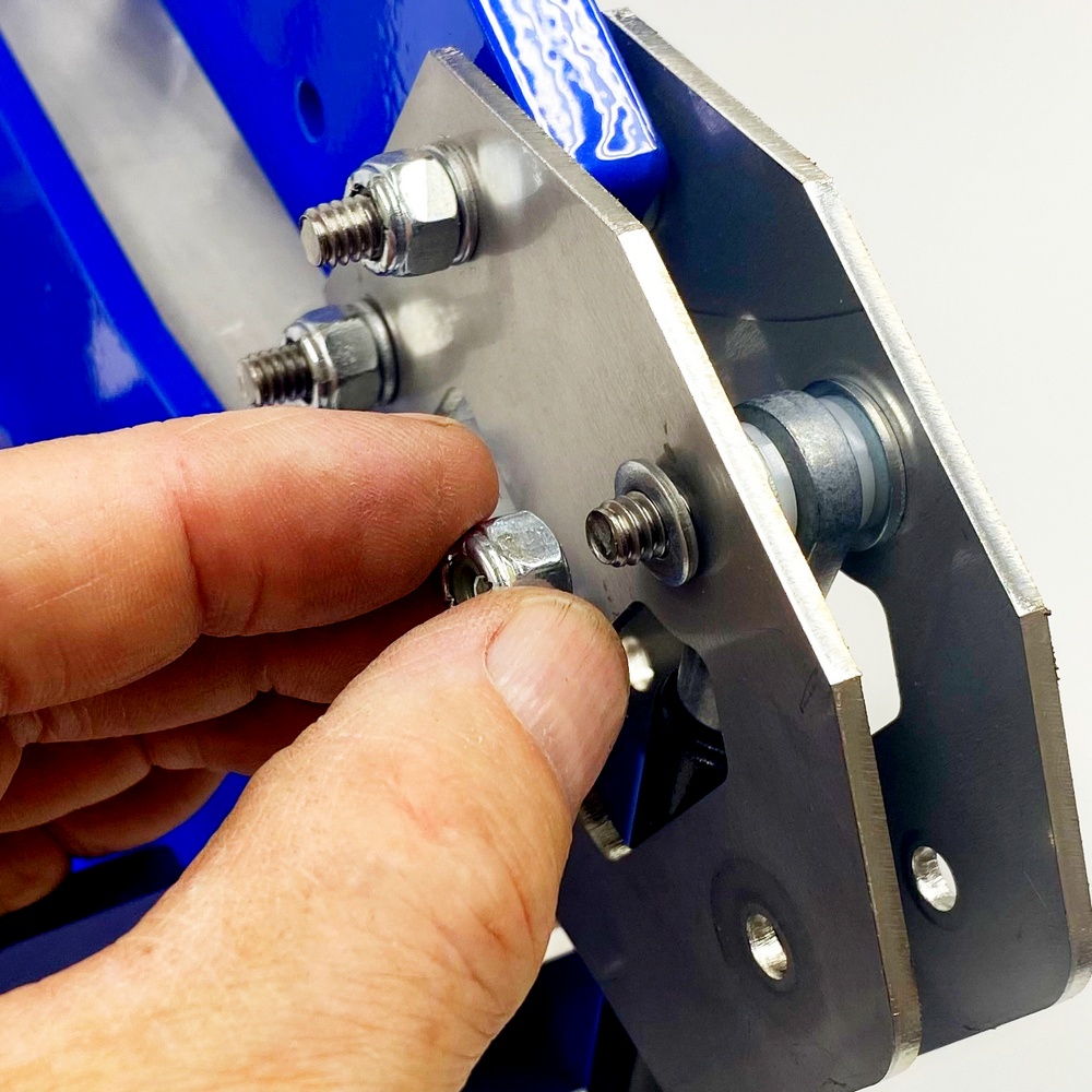
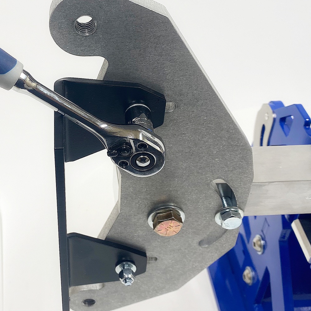
17.3 - Inset the Platen Bracket with Washers and Nuts as pictured |
17.4 - Tighten the Top and Bottom Nuts to secure the Platen Bracket. |
Step 18 - Install the Platen
Bolt Kit 18
|
|
|
|
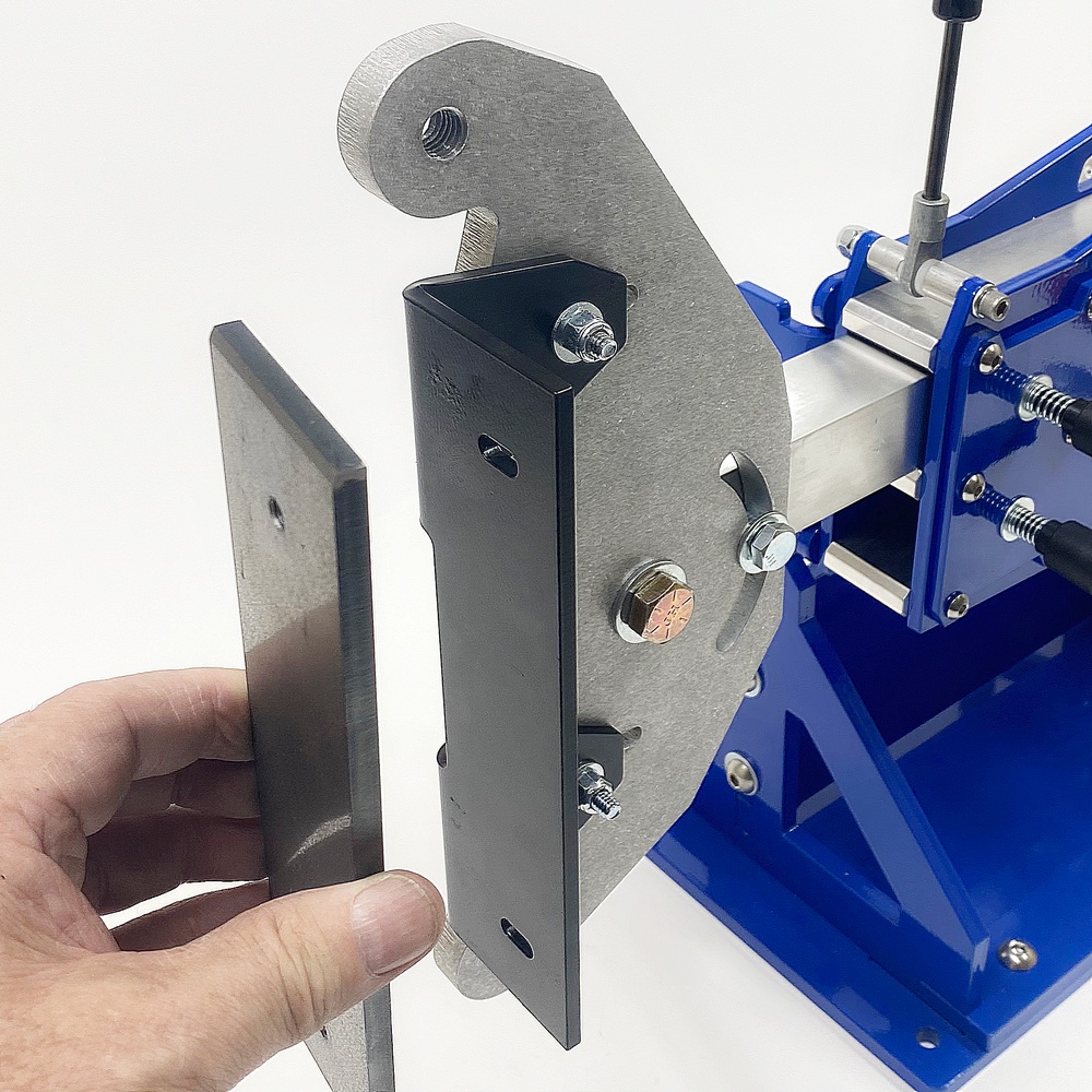
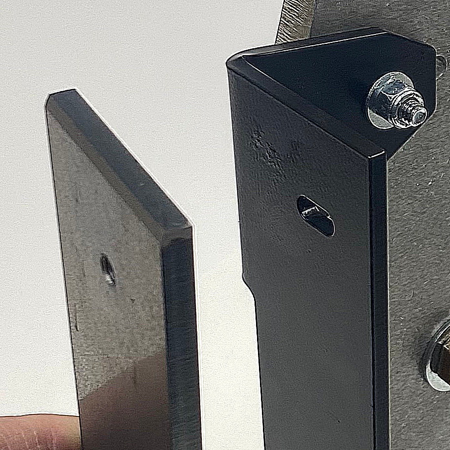
18.1 - Align the Platen Bracket as Pictures |
18.2 NOTE: Make sure the chamfered corners are facing away from the bracket |
|
|
|
|
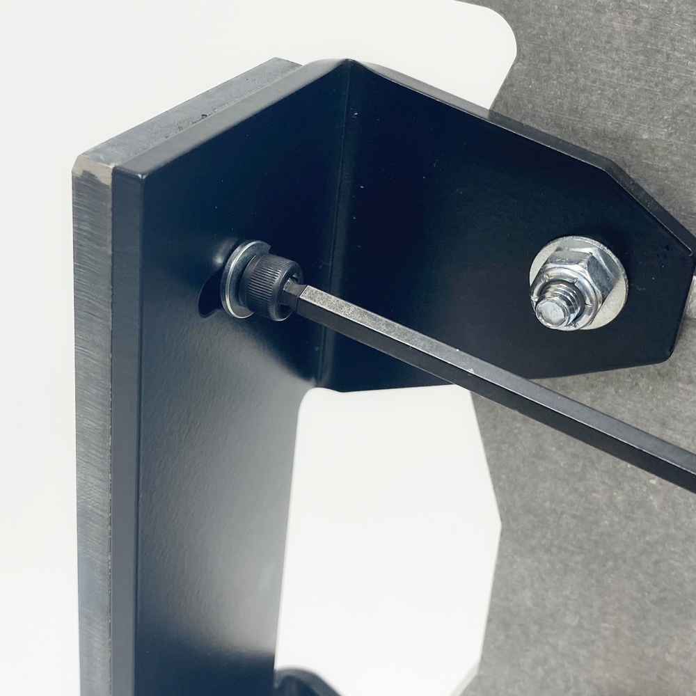
18.3 - Align the Platen to one side of the bracket. Tighten the top and bottom Alen bolts. |
|
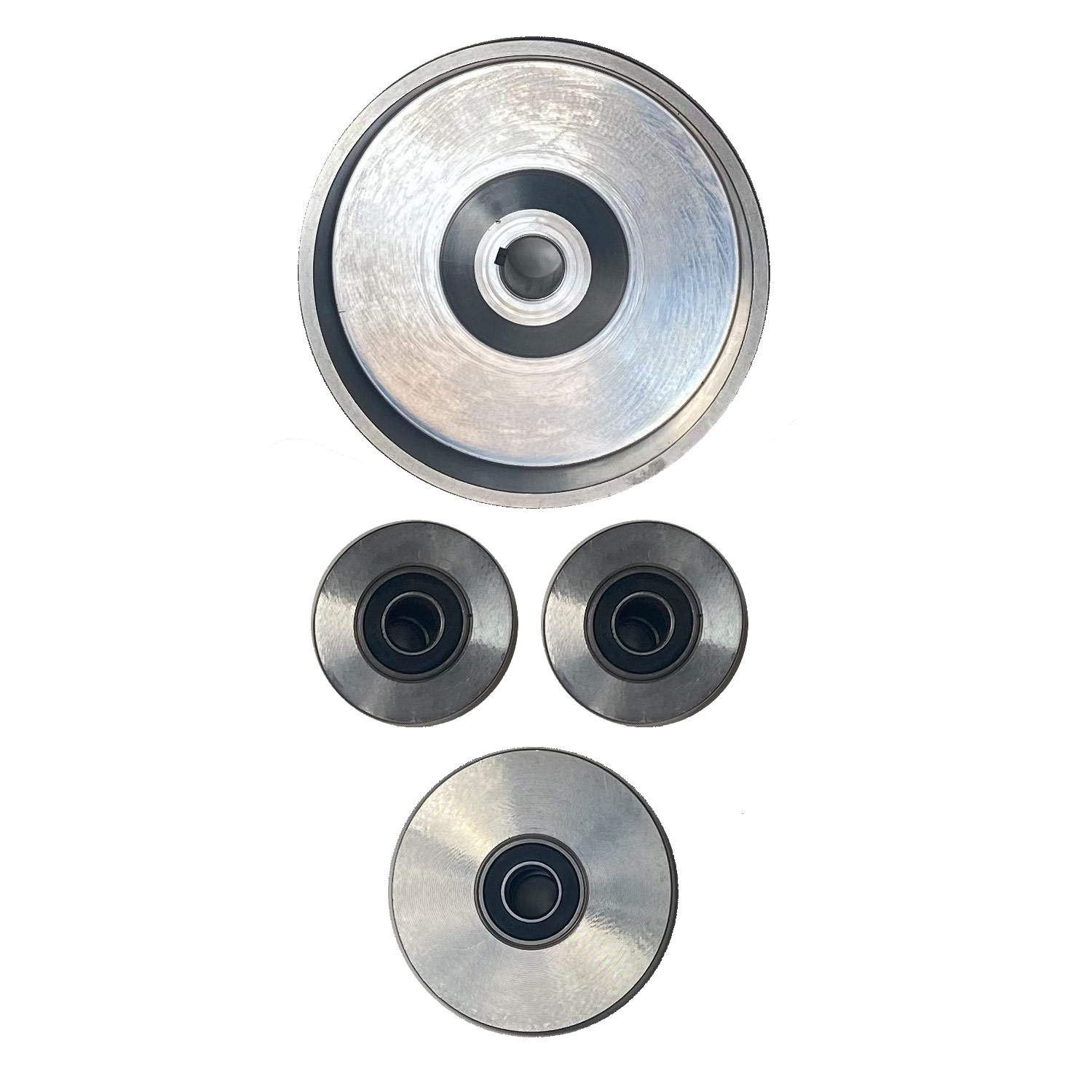
Step 19 - Assemble and Install the Idler Wheels
Bolt Kit 19
|
|
|
|
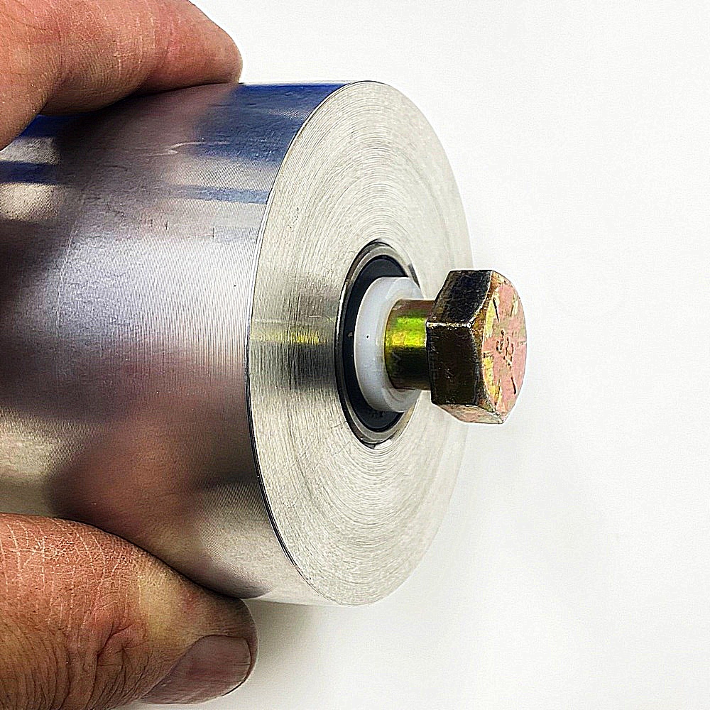
19.1 - Identity the parts for the idler wheel |
19.2 - Insert a Nylon washer onto the bolt, insert the bolt with washer into the idler wheel |
|
|
|
|
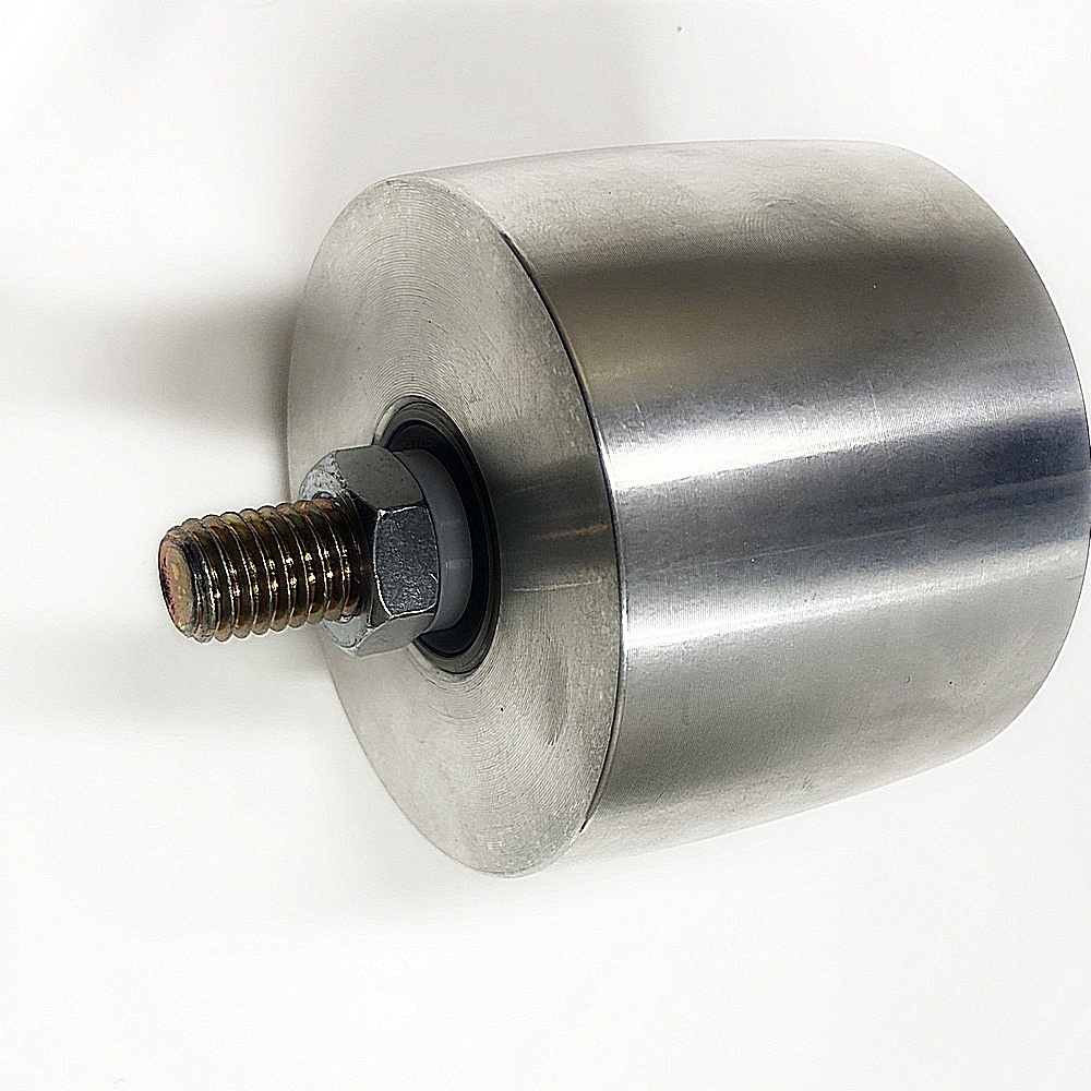
19.3 - Working from the other side install another Nylon washer and large metal washer as pictured |
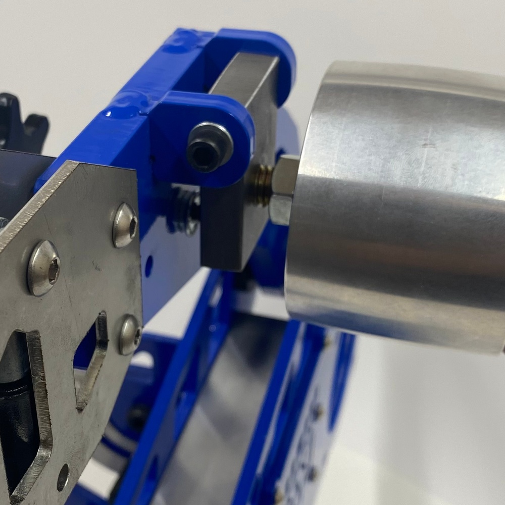
19.4 - Screw the Idler Wheel Assembly into the D-Plate pre-tapped holes |
|
|
|
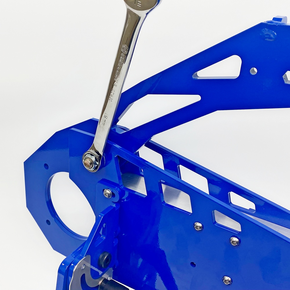
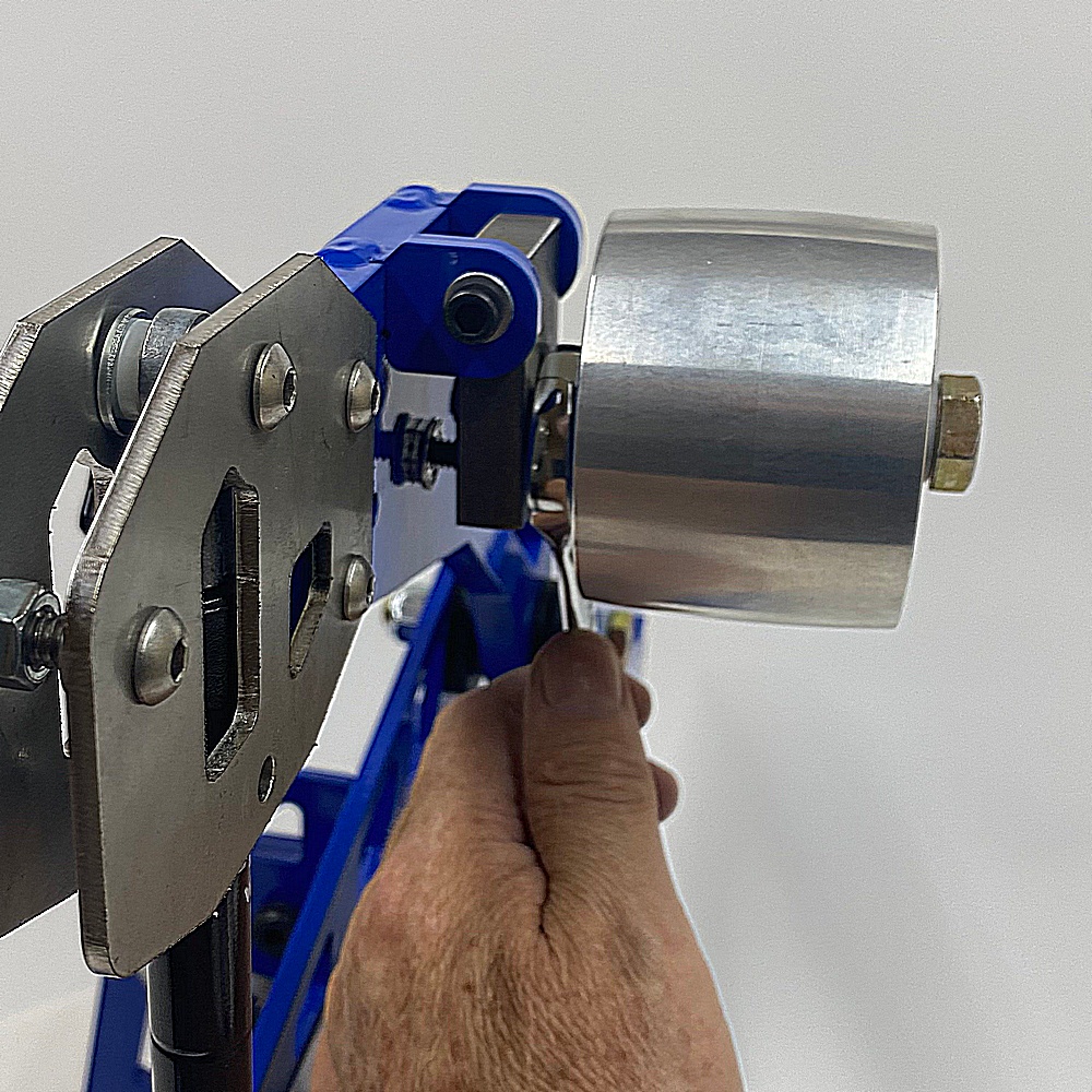
19.5 - Insert the Lock Nut and tighten using a Wrench, use another wrench to hold the bolt in place so it doesn’t turn. Once done the Wheel should be able to spin freely.
IMPORTANT! - Make sure that the wheel spins freely, if the wheel is too tight then loosen the NUT and back out the bolt, then re-tighten the nut.
TIP!: Rather have the wheel to lose than too tight. |
Section 3:
Diktator MAX - Parts Packing List (Box 1)
|
|
BOX 1 |
|||||||||
|
|
BOX 1 |
|||||||||
|
|
BOX 1 |
|||||||||
|
|
BOX 1 |
|||||||||
|
|
BOX 1 |
Diktator MAX - Parts Packing List (Box 2)
|
|
BOX 2 |
|||||||||
|
|
BOX 2 |
|||||||||
|
|
BOX 2 |
|||||||||
|
|
BOX 2 |
|||||||||
|
|
BOX 2 |
|
|
BOX 2 |
||||||||||||
|
|
BOX 2 |
||||||||||||
|
|
BOX 2 |
||||||||||||
|
|
BOX 2 |
||||||||||||
|
|
BOX 2 |
Section 4
Basic Installation & Use Instructions
Diktator MAX Grinder
Basic Installation & Use Instructions
- Bolt the grinder to a sturdy bench with four 3/8" bolts, washers & locknuts. Ensure sufficient overhang so the platen extends over the end of the bench. This allows you to place a water filled bucket on the floor under the platen to catch dust and sparks.
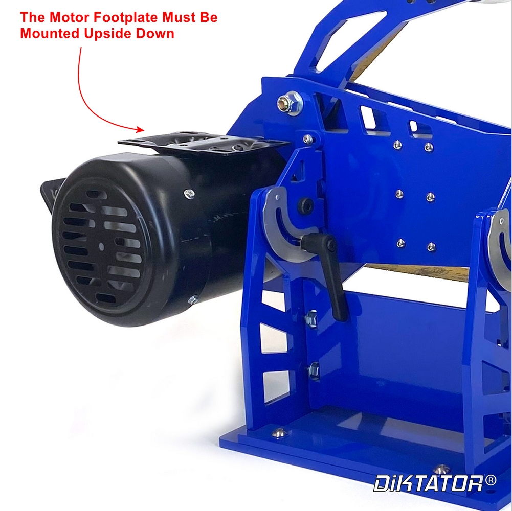
- To install the motor:
- Tilt the grinder 90 degrees into the horizontal position
- Lock the handles
- Place the motor in position directly under the hole in the chassis where it is to be installed
- Make sure that the footplate of the motor is positioned so that it will point straight upwards when the grinder is in the vertical position. So when you’re standing in front of the machine, the motor’s footplate will point to the ceiling & the connector box on the motor will point downwards. See picture below
|
|
- Place blocks of wood or even books under the motor to raise it up into the motor mount.
- Once the motor is in place, carefully insert the motor mount bolts into the motor face holes, being careful not to strip the motor mount holes.
- Once all the motor mount bolts have been turned in a few threads & you’re sure that they have engaged the threads in the motor correctly, start fastening the bolts evenly until the motor is in position.
- Fully tighten all the motor mount bolts.
- Tilt the grinder back & forth between the horizontal & vertical positions a few times to make sure nothing catches & make very sure that no electrical cords can get pinched or hung up.
- If you are using a drive wheel larger than 5” you need to cut a 45 degree wedge out of the back of the tooling arm to clear the motor.
|
IMPORTANT! |
If you are using a larger than 5” tolling arm you need to cut a 45 degree wedge out of the black of the tooling arm or shorten it 1” |
- Install the drive wheel onto the motor shaft. TIP: use a long straight edge such as a yardstick or a length of extruded aluminum, place it on the flat side of the drive wheel and align it with the flat side of the bottom idler wheel.
|
IMPORTANT! |
Always run the belt with the tension arm fully or almost fully compressed for best results. |
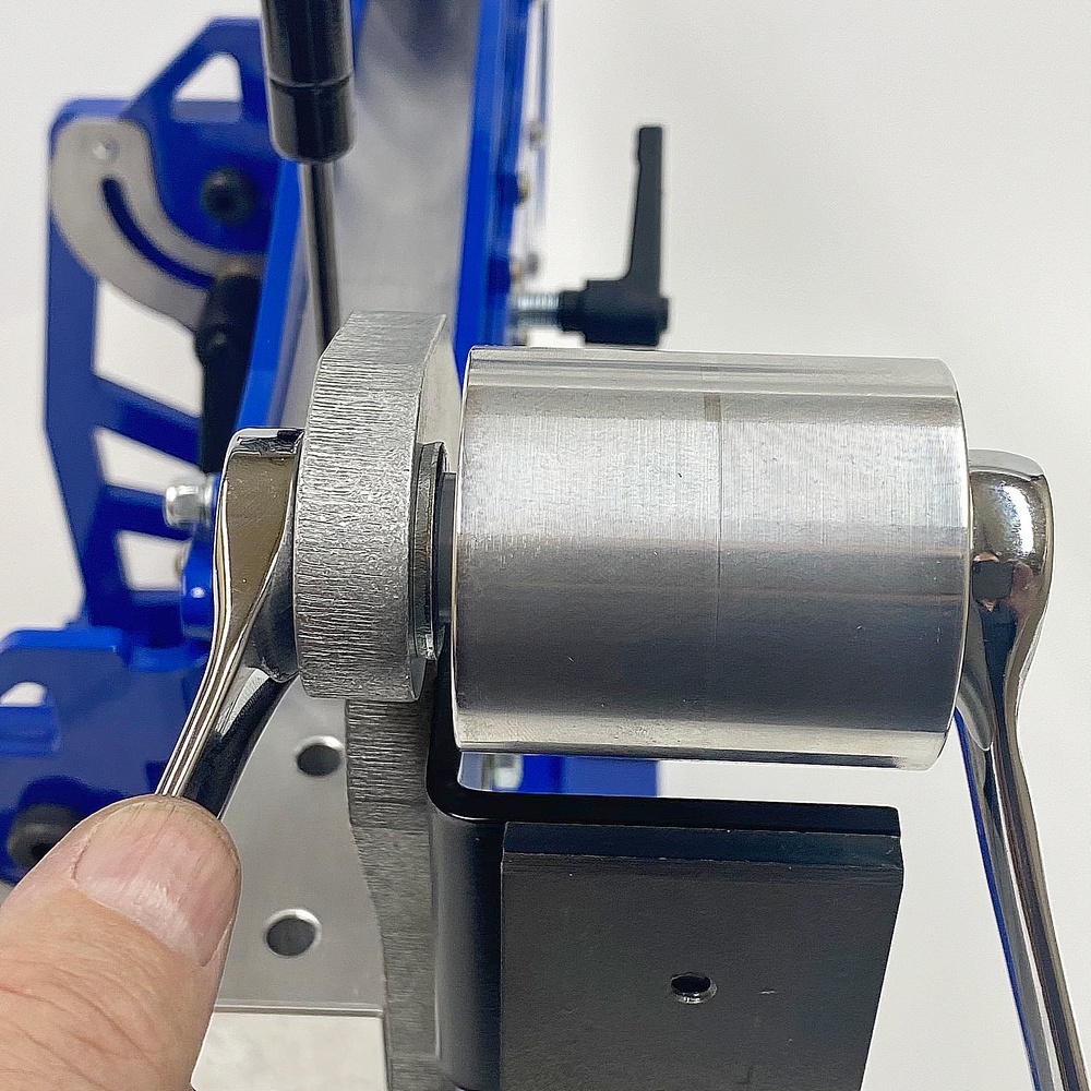
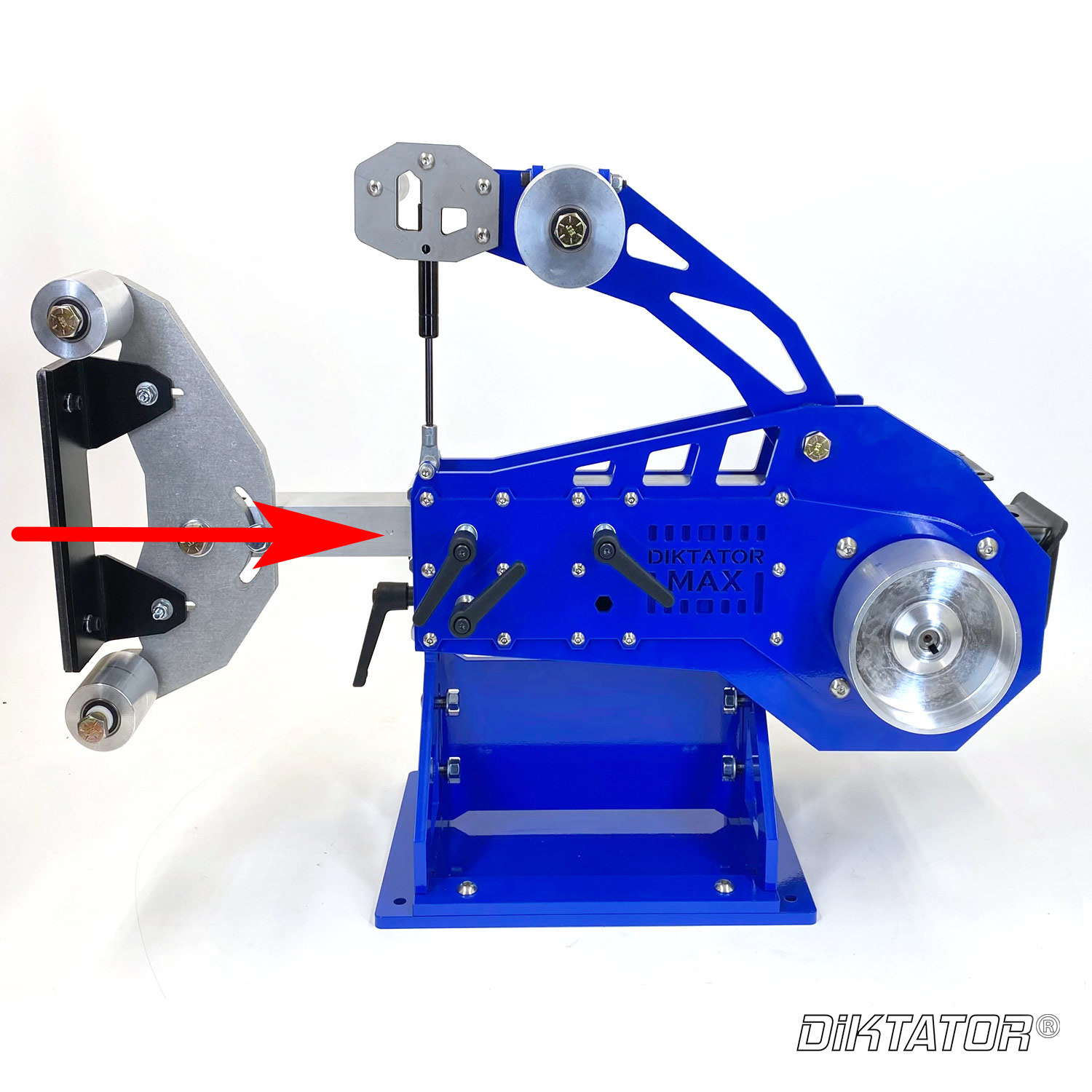
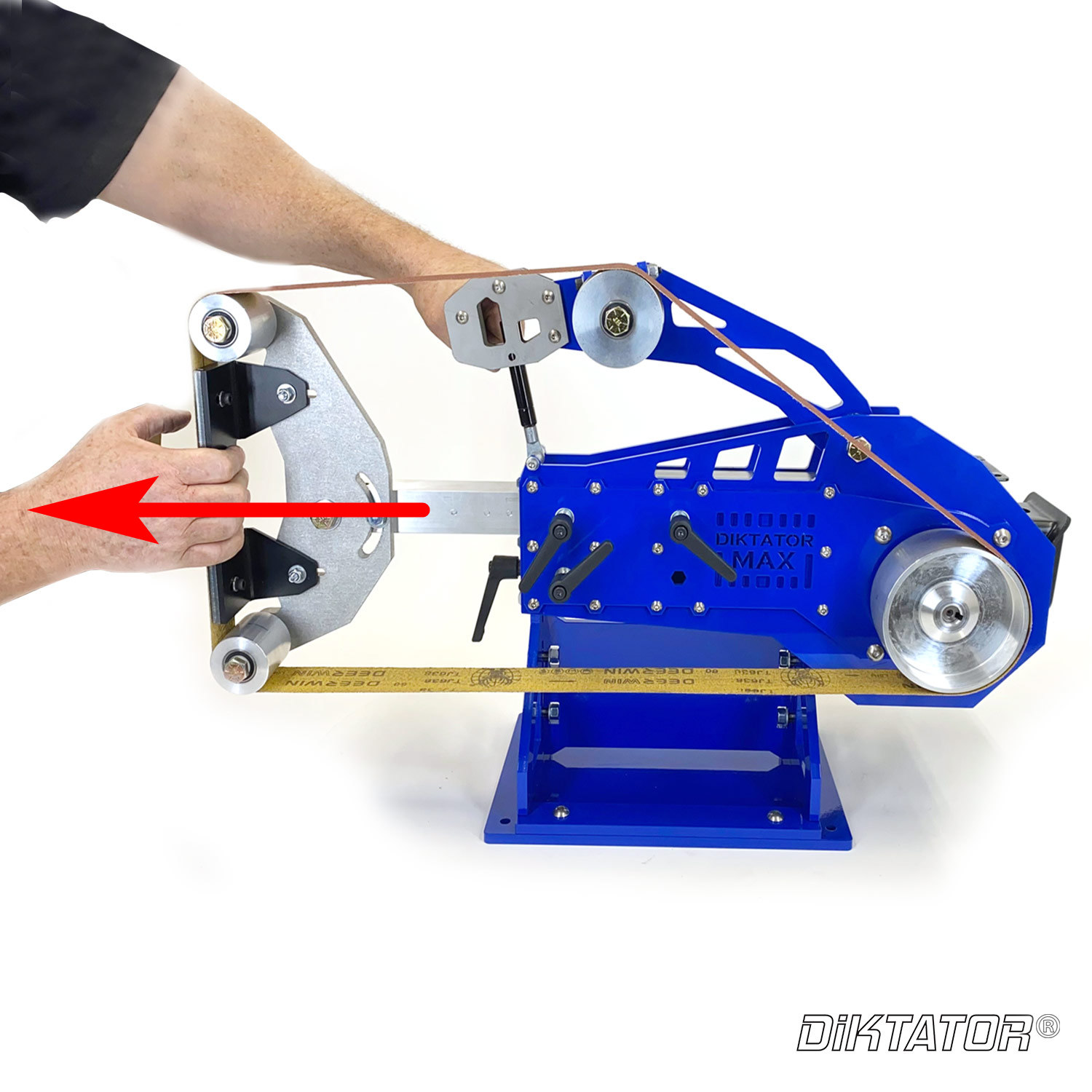
- When installing a new grinding belt, push the tensioning arm all the way down, then pull the tooling arm all the way out until the belt is tensioned. Secure the tooling arm clamp knob. Always run the belt with the tension arm fully or almost fully compressed for best results, see images below.
|
|
|
|
Step 1 - Loosen the Tooling Arm locking levers and push it all the way in towards the motor as far as it would go. |
Step 2 - Push down on the tension arm with one hand and place the belt over all the wheels as pictured. Notice the slack in the belt hanging loose at the bottom |
|
|
|
|
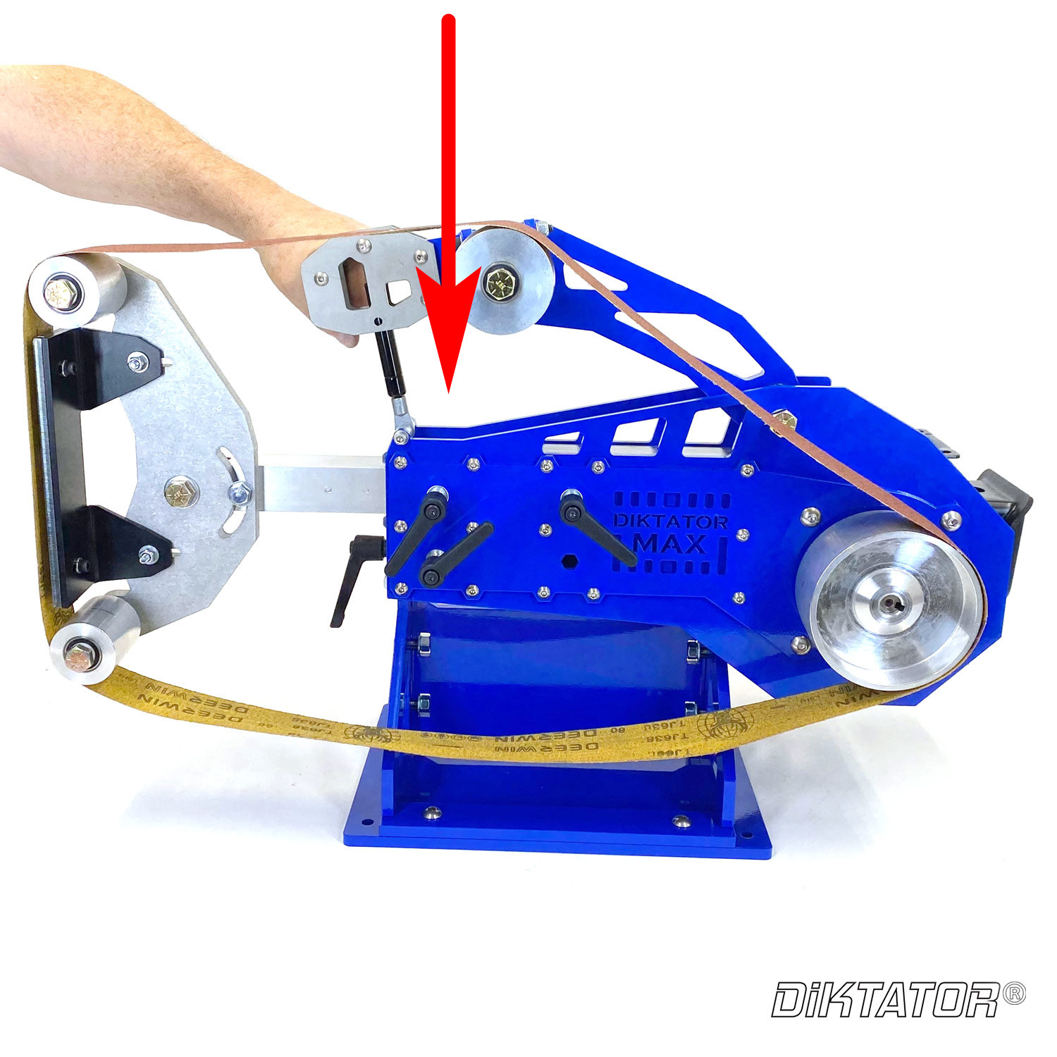
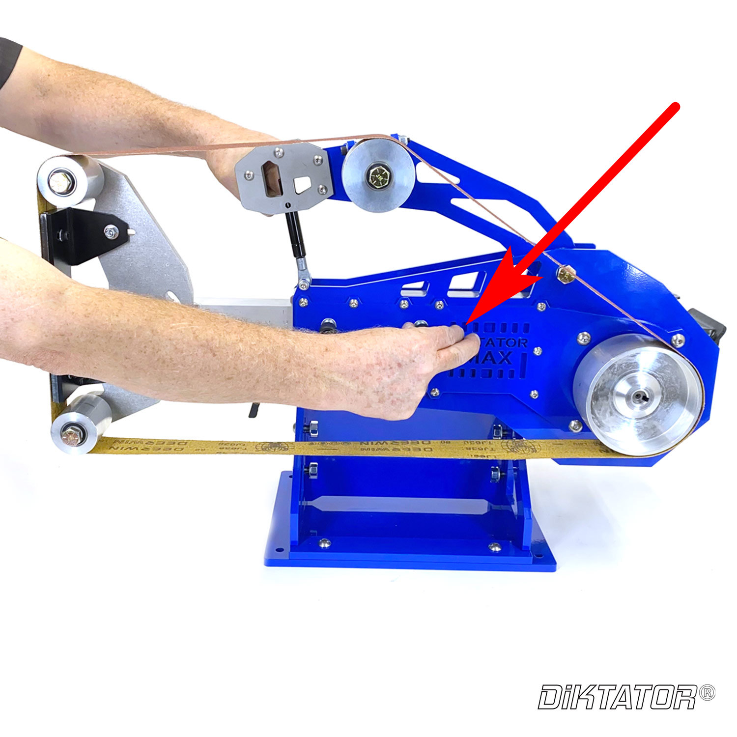
Step 3 - With the tension arm still compressed, use your other hand to pull the tooling arm out towards you. |
Step 4 - With the tension arm still compressed with one hand, tighten the locking lever on the tooling arm to lock it in place and let go of the tension arm. |
- Always hand track the belt a few times (use the bottom free belt area between the lower idler wheel & the drive wheel for this) first to ensure the new belt runs true on the wheels and will not run off to either side when starting the motor.
- Grinding releases dust which should not be breathed in! Always wear respiratory protection.
- Grinding gives off sparks, dust, and debris which can cause eye & face damage! Wear goggles AS WELL AS a grinding face shield.
- Grinding is loud! Wear hearing protection.
- Grinding causes objects to get hot! Wear hand protection.
- Grinding metal can form very sharp edges, especially when grinding knives! Beware of flying objects; wear hand protection and preferably a heavy-duty leather apron and work boots.
- Grinding can give off sparks which can melt or even set fire to anything flammable near the grinder. Be especially careful when using dust suction devices including vacuum cleaners: DO NOT allow such devices to ingest hot embers or hot steel shards.
- Ensure the bench is always clear of clutter and obstructions that could contact the belt or wheels.
- Ensure you have easy access to the on/off switch of the motor at all times.
- Carefully read & adhere to all warnings located in the placards on the machine
- Ensure that no electrical cable can be pinched or come into contact with the grinding belt
|
Warning! |
Observe the warning of objects being flung from the machine, most likely when in the horizontal position |
- Please observe especially the warning about the possibility of objects being flung from the machine, most likely when in the horizontal position. Consider the possible path of such objects carefully: MAKE SURE YOU GRIND IN A SAFE DIRECTION & THAT YOU HAVE A SAFE BACKSTOP
- When using the belt without the platen & backing plate (free grinding), be aware that the belt builds up significant static electricity: GROUND the piece that's being worked with a crocodile clamp and wire.
- Never ever operate this grinder without having it securely bolted to a sturdy bench. Never operate this grinder near flammable materials.
- Always use common sense when grinding and ask for help if you're unsure. Happy grinding
Section 6:
Troubleshooting and Maintenance Guide
|
Symptom |
Possible Solutions |
|
The Tooling Arm is to long |
(1) Move the Gas Strut to the TOP position to get a longer travel range. |
|
(2) If you are using a larger than 5``drive wheel then you can shorten the tooling arm by 1” or cut a 45 degree wedge out of the black of the tooling arm. |
|
|
The belt wobbles across the platen |
Belt wobble is very common, it's caused by skew cut belts. You can true up the edge of a belt by running a piece of steel into it until the wobble stops; you can then remove & reinstall that belt & the trued edge will continue to run true. |
|
The belt is not tracking |
Make sure there is tension on the belt, see section 4.3 |
|
The Motor keeps on tripping the power
|
(1) Test the circuit using a very inexpensive outlet tester which you can purchase from your local hardware store (see picture below)
|
|
(2) Make sure the motor is not connected to a GFCI outlet as they are more sensitive to current limits vs a traditional outlet. |
|
|
(3) Make sure the motor is not connected to a GfCI circuit breaker (mounted in the breaker or electrical panel) as they are more sensitive to current limits vs a traditional outlet. |
|
|
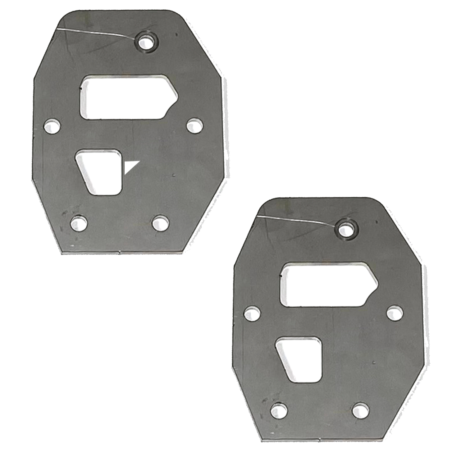
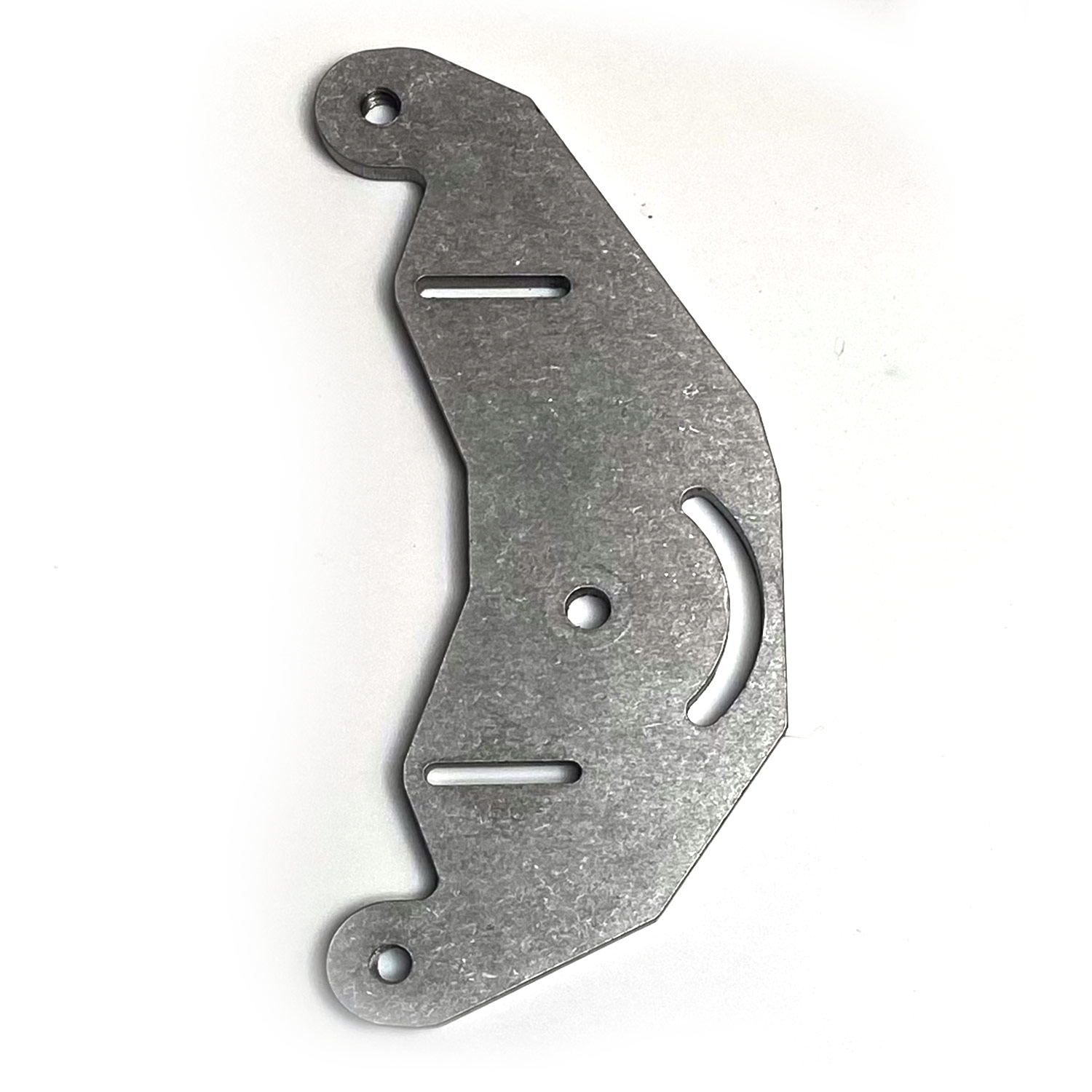
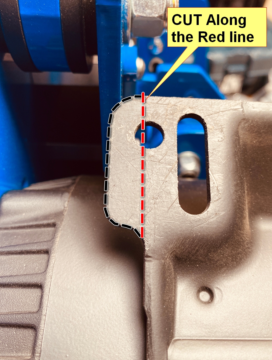
The motor does not fit if mounted upside down (with the footplate facing up) |
In some cases, the electric motor manufacturer might change the design on the footplate. The fix is to mark and cut the footplate as pictured below. |
|
|

www.DiktatorGrinder.com Copyright © Diktator Grinder | All Rights Reserved
- Choosing a selection results in a full page refresh.